
Connector

a technology of connecting rods and connectors, applied in the direction of couplings/cases, coupling device connections, electrical devices, etc., can solve the problems of difficult assembly of the cover, difficult positioning of the cover, etc., and achieve the effect of smooth assembly of the cover

Active Publication Date: 2012-08-28
SUMITOMO WIRING SYST LTD
View PDF4 Cites 15 Cited by
  • Summary
  • Abstract
  • Description
  • Claims
  • Application Information

AI Technical Summary

Benefits of technology

Enables smooth assembly of the cover, prevents wire entanglement, and increases construction flexibility by guiding the cover's position and movement, ensuring proper alignment without immediate engagement, thus simplifying the assembly process.

Problems solved by technology

It is difficult to position the cover at a sliding movement starting position on the housing.
Particularly, if the lever already is mounted on the housing, the cover interferes with the lever and it is hard to assemble the cover.

Method used


Image

  • Connector
  • Connector
  • Connector

Examples


Embodiment Construction

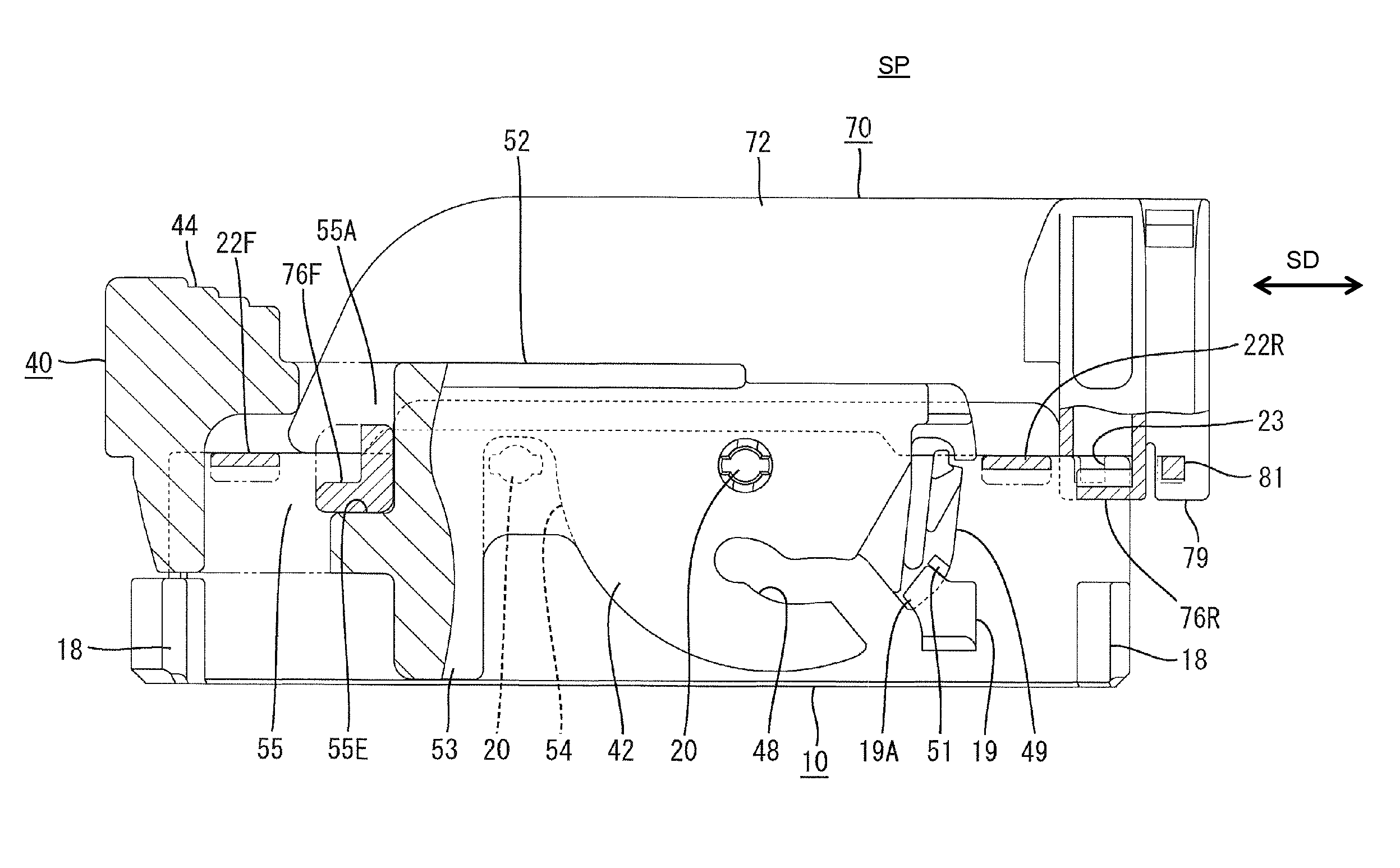
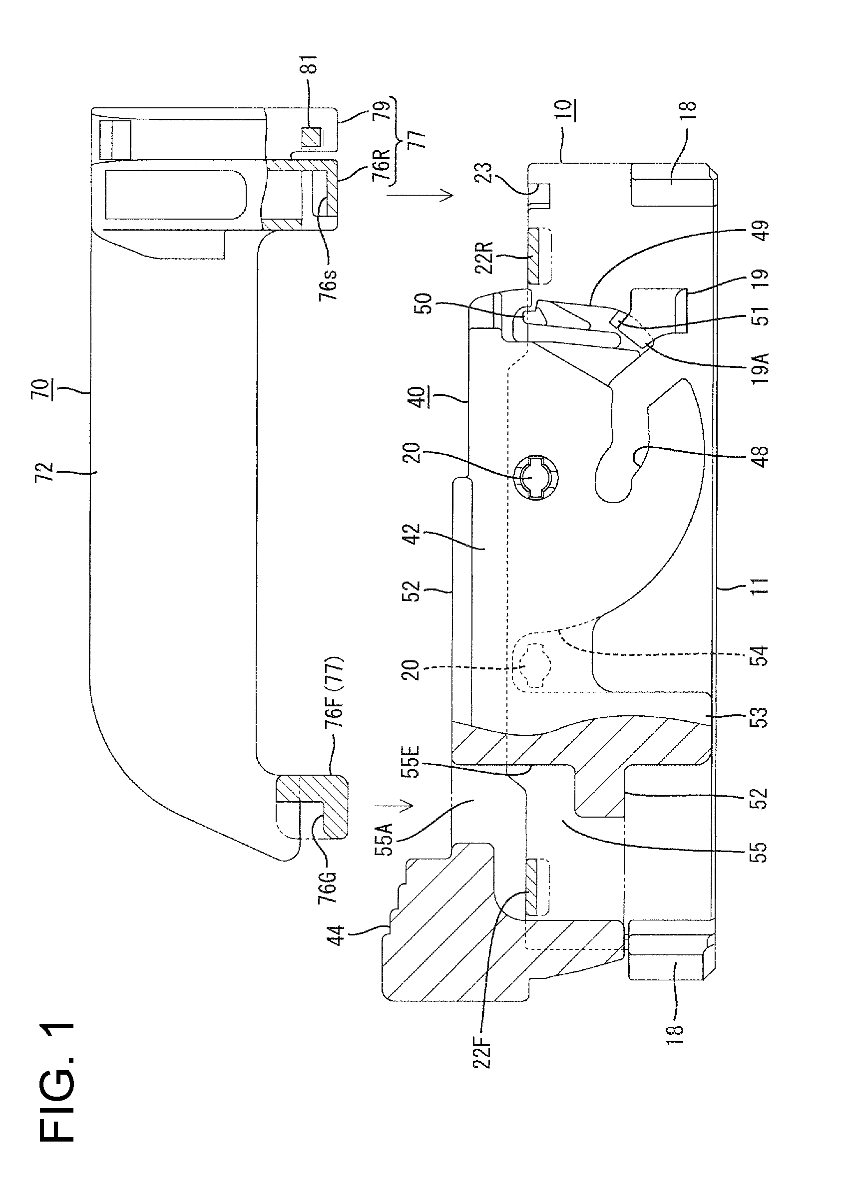
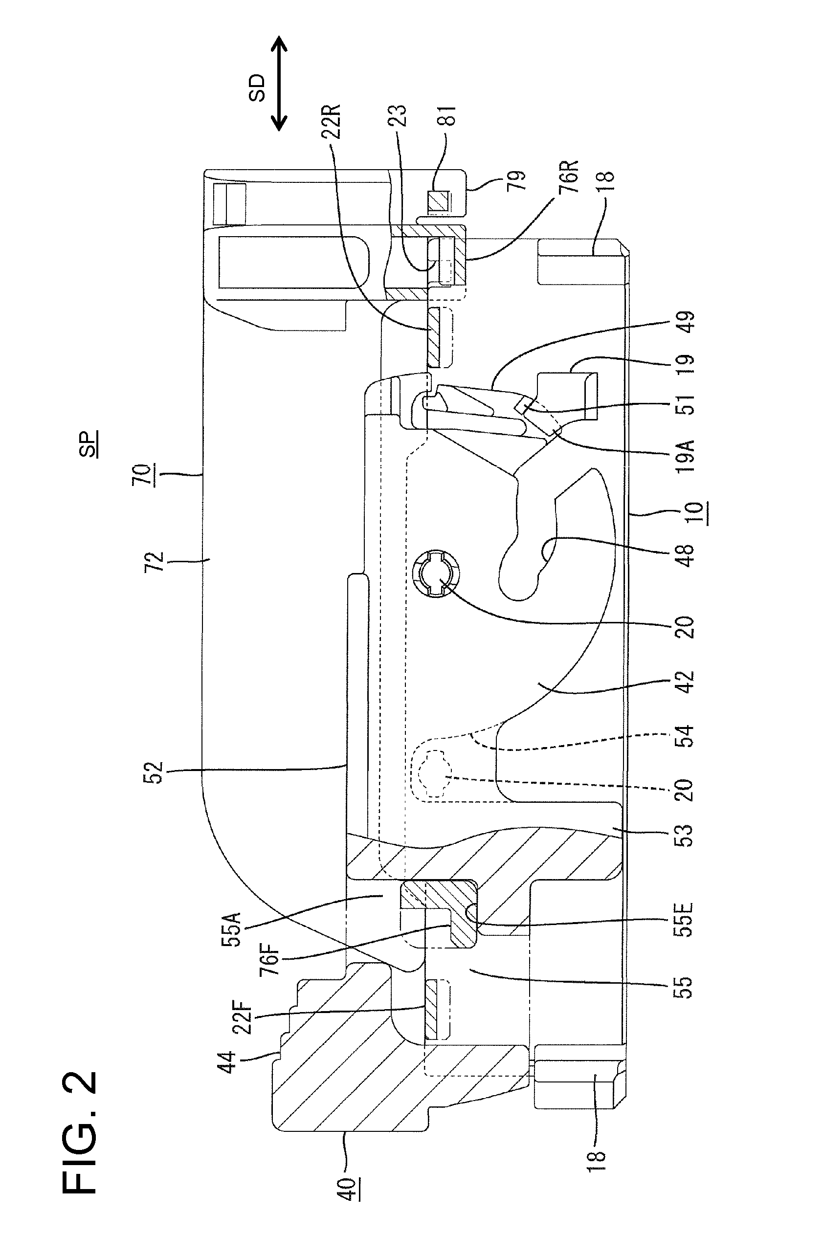
[0030]One particular embodiment of the present invention is described with reference to FIGS. 1 to 13. A connector according to this embodiment includes a housing 10, a lever 40 as a movable member and a cover 70. The housing 10 and the lever 40 form part of a connector member. The housing is connectable to a mating housing 100.

[0031]The mating housing 100 is made e.g. of synthetic resin and includes a receptacle 110 in the form of a narrow substantially rectangular tube that is long in a width direction, as shown in FIG. 5. Claw-shaped engaging portions 112 project from the inner surfaces of the front ends of the side walls 111 of the receptacle 110. Left and right substantially cylindrical cam followers 113 project on the inner surface of the each of the upper and lower walls of the receptacle 11 at opposite sides of a widthwise center. Unillustrated male tabs are arranged to project into the receptacle 110.

[0032]The housing 10 is made e.g. of synthetic resin and includes a housin...


PUM


Abstract

A connector member is formed with first slides (22F, 22R) and first locks (23). A cover (70) is formed with second slides (76F, 76R) and second locks (79). The cover (70) is mounted on the connector member slidably between a standby position and a mount position. The first and second slides (22F, 22R) and (76F, 76R) slide on each other to guide a sliding movement of the cover (70) from the standby position to the mount position. At the mount position, the first and second locks (23, 79) engage to prevent a returning movement of the cover (70) to the standby position. The connector member is formed with guide paths (55) for positioning and guiding the cover (70) to the standby position.

Description

BACKGROUND OF THE INVENTION[0001]1. Field of the Invention[0002]The invention relates to a connector.[0003]2. Description of the Related Art[0004]Japanese Unexamined Patent Publication No. 2005-116209 discloses a conventional connector. The connector includes a block-shaped housing with front and rear ends. Wires are drawn out from the rear end and a cap-shaped cover is mounted on the rear end of the housing for covering the wires. A rotatable lever is mounted to straddle the housing. The lever is rotated across a rear side of the cover and the housing to connect with a male housing.[0005]It is difficult to position the cover at a sliding movement starting position on the housing. Particularly, if the lever already is mounted on the housing, the cover interferes with the lever and it is hard to assemble the cover.[0006]The invention was developed in view of the above situation and an object thereof is to enable a cover to be smoothly mounted.SUMMARY OF THE INVENTION[0007]The inventi...

Claims


Application Information

Patent Timeline
Patent Type & Authority Patents(United States)
IPC IPC(8): H01R13/44
CPCH01R13/62938H01R13/506
Inventor SHAMOTO, WATARUMAKINO, KENJI
Owner SUMITOMO WIRING SYST LTD
Learn More