Damping system

a technology of damping system and damping spring, which is applied in the direction of vehicle springs, resilient suspensions, load-carrying vehicle superstructures, etc., can solve the problems of adversely affecting triggering precision, and achieve the effect of simplifying damping

Active Publication Date: 2012-08-14
HYDAC SYST
View PDF3 Cites 4 Cited by
  • Summary
  • Abstract
  • Description
  • Claims
  • Application Information

AI Technical Summary

Benefits of technology

[0003]An object of the present invention is to provide a simplified damping system allowing variable adjustment of constant damping ratios with few insert parts and components.
[0004]This object is basically achieved by a damping system where proportional damping for the respective actuating part of the damping system is achieved by a proportional throttle valve providing the only fluid communication between the actuating part and an accumulator. Variable proportional damping can be accomplished, compared to current solutions with constant damping, having the advantage of being able to react to events depending on the situation and in a manner specific to the user. By using the proportional throttle valve, it is possible to variably choke the respectively hydraulically triggerable actuating part with only one triggering process without hysteresis phenomena occurring in the actual damping process. This arrangement could adversely affect triggering precision. Compared to known solutions, the damping system according to the present invention also requires less control effort and only little space. The damping system solution according to the present invention can also be economically implemented and reliably operated.
[0005]In one especially preferred embodiment of the damping system according to the present invention, the proportional throttle valve interworks with nonreturn valves and, via the nonreturn valves, the trigger side of the actuating part not being damped can accept oil from the hydraulic accumulator, counteracting the danger of cavitation in the hydraulic circuit, as otherwise often occurs in the prior art damping systems. In an especially advantageous manner, cavitation is avoided where the proportional throttle valve with the nonreturn valves forms a type of hydraulic rectifier circuit.

Problems solved by technology

This arrangement could adversely affect triggering precision.

Method used


Image

  • Damping system
  • Damping system
  • Damping system

Examples


second embodiment

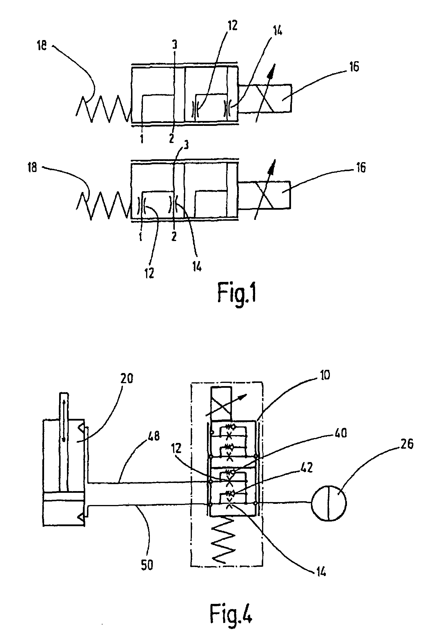
[0019]In the modified or second embodiment as shown in FIG. 4, the nonreturn valves 40, 42 are connected in a parallel configuration to the assignable chokes 14, 12. By using the respective integrated nonreturn valves 40, 42, additional fluid lines can be dispensed with and the proportional throttle valve 10 can be connected directly via the fluid lines 48, 50 to the rod side or piston side of the actuating part 20 in the form of the power cylinder.

third embodiment

[0020]The modified or third embodiment shown in FIGS. 5 and 6 is explained only to the extent it differs significantly from the preceding embodiments. FIG. 5 shows a deflection process, comparable to FIG. 2. FIG. 6 shows a rebound process comparable to FIG. 3. The proportional throttle valve 10 includes only one choke 14. The parallel choke 12 located in the secondary branch is not necessary in the embodiment shown in FIGS. 5 and 6. Instead, two additional nonreturn valves 52 and 54 are used. The pairs of nonreturn vales 40, 42 and 52, 54 are interconnected in the manner of a hydraulic rectifier circuit together with the proportional throttle valve 10. The fluid lines 48 and 50 connected to the actuating part 20 each discharge between two adjacent nonreturn valves 42 and 54 and 40 and 52. In the opening direction the nonreturn valves 52 and 54 are placed on the connection side 2 of the valve 10 via the corresponding fluid lines 56. Conversely, the port 3 is connected in turn to the ...


PUM


Abstract

A damping system, in particular in the form of a hydraulic cabin spring system, has at least one hydraulically triggerable actuating part (20) and has at least one hydraulic accumulator (26) connected to the actuating part (20). By a proportional throttle valve (10), proportional damping for the actuating part (20) is achieved. Variable proportional damping which can react to events in a manner specific to the user can be implemented.

Description

FIELD OF THE INVENTION[0001]The present invention relates to a damping system, in particular in the form of a hydraulic cabin spring. The system has at least one hydraulically triggerable actuating part and at least one hydraulic accumulator connected to the actuating part.BACKGROUND OF THE INVENTION[0002]Damping or spring systems are readily available in the market in a plurality of embodiments. In addition to a cabin spring system for vehicles, other hydraulically triggerable actuating parts can be designed with damping, such as, for example, hydraulic motors for drive units. In the known solutions, to obtain uniform or constant damping, high control effort is necessary to detect the hydraulic state of the respectively triggerable actuating part and / or its position using correspondingly designed sensors.SUMMARY OF THE INVENTION[0003]An object of the present invention is to provide a simplified damping system allowing variable adjustment of constant damping ratios with few insert p...

Claims


Application Information

Patent Timeline
Patent Type & Authority Patents(United States)
IPC IPC(8): B60G11/18
CPCB60G17/08F16F9/46B62D33/0608F16F9/096B60G2202/24B60G2204/162B60G2202/154
Inventor SCHOLL, JOSEPH
Owner HYDAC SYST
Why Eureka
Try Eureka