
Method and apparatus of breathing-controlled electrical stimulation for skeletal muscles

a technology of electrical stimulation and skeletal muscles, applied in the field of electric stimulation of skeletal muscles, can solve the problems of limiting the application imposing other problems, including convenience, compliance and cost, and controversial effect of current electrical stimulation techniques on spasticity reduction

Active Publication Date: 2012-07-24
BOARD OF RGT THE UNIV OF TEXAS SYST
View PDF7 Cites 10 Cited by
  • Summary
  • Abstract
  • Description
  • Claims
  • Application Information

AI Technical Summary

Benefits of technology

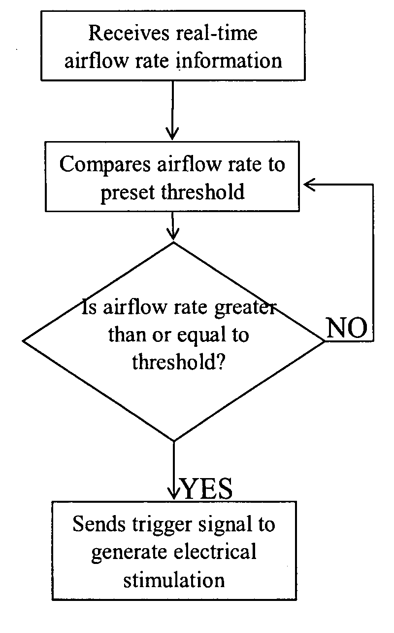
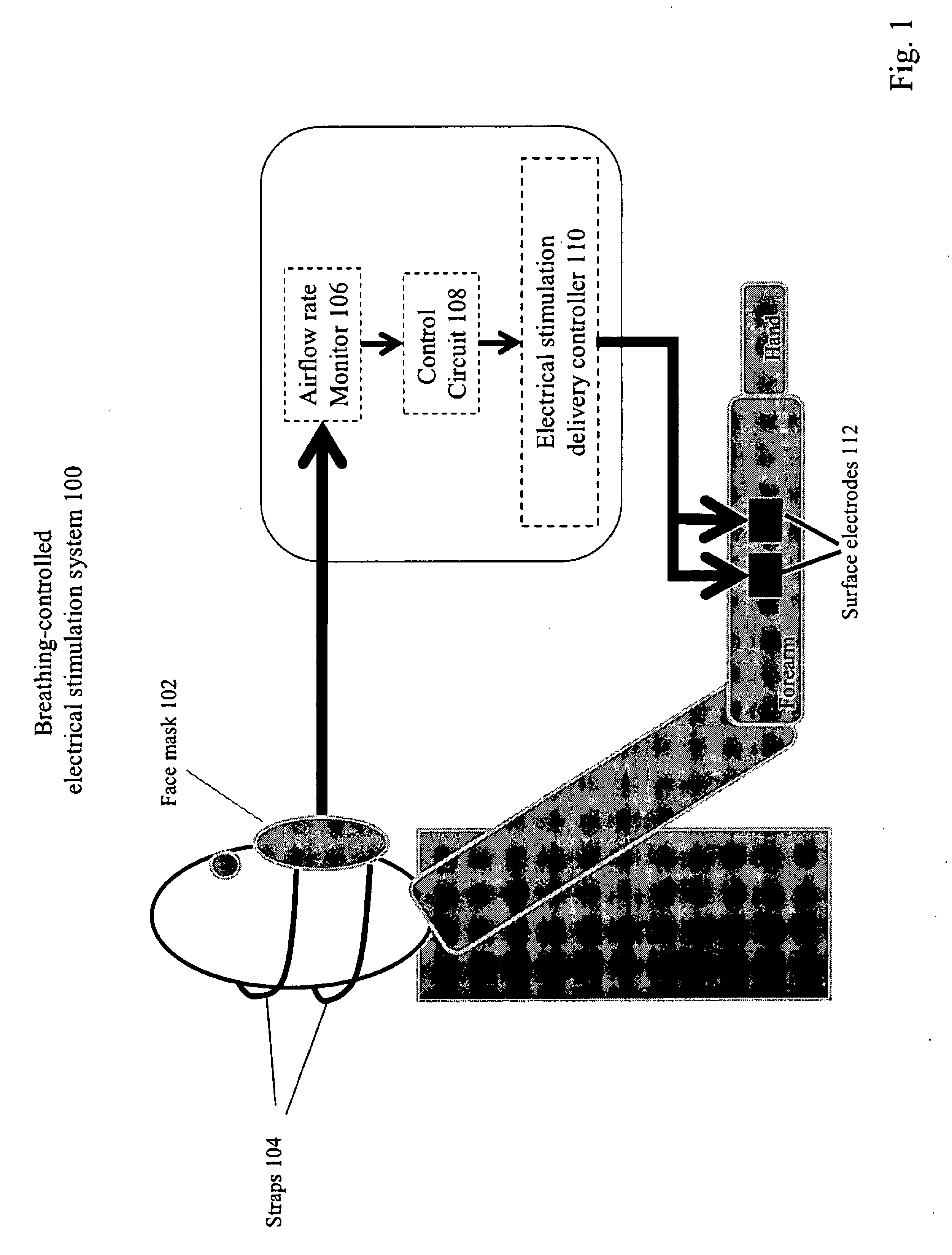
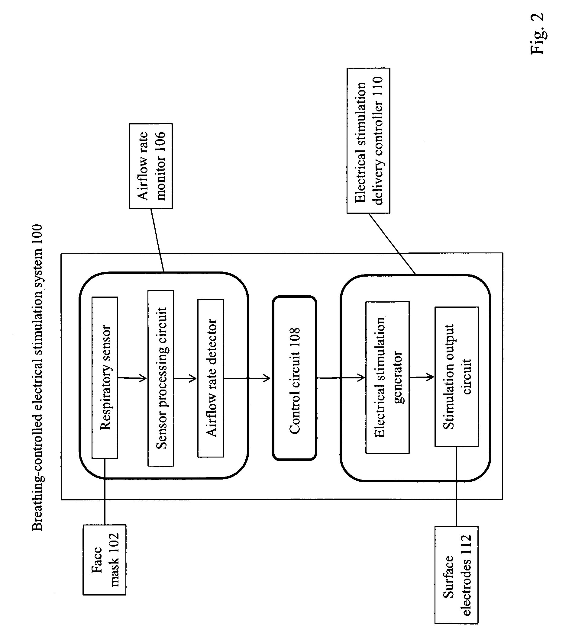
"The patent describes a device and method for delivering electrical stimulation to target muscles in a way that synchronizes with a patient's breathing. This can be used for rehabilitation after a stroke or for performance enhancement in healthy individuals. The device collects a patient's respiratory signal and interprets it to detect the patient's breathing pattern. The device can deliver electrical stimulation to the patient's muscles when the breathing pattern is detected. The method and device can be used with different populations, including stroke patients, traumatic brain injury patients, and healthy individuals. The technical effects include improved effectiveness of neuromuscular electrical stimulation and avoidance of excessive coactivation problems."

Problems solved by technology

Common post-stroke hand function impairments include a stereotypically flexed resting posture of the wrist and fingers and an inability to extend fingers voluntarily.
However, the effectiveness of current electrical stimulation techniques on spasticity reduction remains controversial (Stackhouse 2008).
This requirement limits its application, especially for patients with moderately to severely impaired finger extension.
This may be problematic when surface EMG signals are utilized.
Though improved by using intramuscular EMG signals, this technique imposes other problems, including convenience, compliance and cost.
Lastly and most importantly, inappropriate coactivation of finger flexors and extensors may cause serious problems when using assisted electrical stimulation (Kamper and Rymer 2001).
Kamper and Rymer observed that attempts of voluntary metacarpao-phalangeal (MCP) joint extension actually resulted in MCP joint flexion in some hemiparetic patients (Kamper and Rymer 2001).
The clinical applications of EMG-triggered electrical stimulation for wrist / finger motor recovery are thus limited, and similar drawbacks to those discussed above are associated with EMG-triggered electrical stimulation in the other applications for which it is available.
Moreover, as noted, passive neuromuscular stimulation has been found inferior to EMG-triggered stimulation for motor recovery.

Method used


Image

  • Method and apparatus of breathing-controlled electrical stimulation for skeletal muscles
  • Method and apparatus of breathing-controlled electrical stimulation for skeletal muscles
  • Method and apparatus of breathing-controlled electrical stimulation for skeletal muscles

Examples


example 1

[0044]Data from one study is shown in FIG. 5, which supports that the most effective response to electrical stimulation can be achieved during forced inspiration. In particular, FIG. 5 shows an example response from a stroke patient when a single electrical pulse is delivered to the finger extensors during three different breathing conditions. The stroke patient (male, 75 years of age, right CVA / left hemiplegia for 22 years) had intact sensation and weak voluntary finger extension. During the electrical stimulation treatment, the patient was seated in a comfortable position in a chair with the impaired forearm stabilized in the neutral position. The patient's wrist was also stabilized in the neutral position using Velcro stripes. The mid-shafts of proximal phalanges were stabilized against four force sensors such that the metacarpophalangeal (MCP) joints were in approximately 30 degrees of flexion. The maximal finger extension force measured at MCP joints was 11.1 Newtons. The patie...

example 2

[0047]Data from another study is shown in FIG. 6, which supports the positive rehabilitation effect of breathing-controlled electrical stimulation intervention. In particular, FIG. 6 shows example responses from another stroke patient before and after a 25 minute breathing-controlled electrical stimulation intervention. The patient (male, 60 years of age, left CVA / right hemiplegia for 2 years and 2 months) had intact sensation but was without voluntary finger / wrist extension. The same experimental set-up was used for this patient as described above in the context of FIG. 5. The procedure differed from that described above. The patient was directed to initiate repeated forced inspiration, as opposed to the three breathing conditions above, and electrical stimulation was delivered only under the Inspiration condition. Single electrical pulses were triggered and delivered to his right finger extensors each time the inspiration airflow rate reached 2.0 L / s, 40% of the patient's maximal ...

example 3

[0050]A pilot study with a chronic traumatized brain injury (TBI) patient demonstrated significant spasticity reduction. The patient (male, 27 years of age, left hemiplegia resulted from TBI for 13 years) had intact sensation of the left forearm and hand and no voluntary wrist / finger extension. The Modified Ashworth Scale of left finger flexors was 3 (0: normal, 4: fixed posture due to hypertonia). The patient received approximately 25 min of breathing-controlled electrical stimulation using the same protocol as described in Example 2. The intensity of electrical stimulation was 140 V. The duration of pulse was 0.1 ms. The preset inspiration airflow rate was 2.0 L / s, equivalent to 50% of the measured maximal inspiration airflow rate (4.0 L / s). The patient reported loosening of his left finger flexors immediately after the treatment, and the Modified Ashworth Scale was 2. This significant reduction in finger flexor hypertonia was retained until the end of 4-week follow-up from his tr...


PUM


Abstract

Methods and devices are provided such that electrical stimulation can be delivered to a patient's skeletal muscles in response to certain respiratory signals, such as when voluntary breathing is detected.

Description

GRANT SUPPORT DISCLOSURE[0001]This invention was made, at least in part, with funding from the National Institutes of Health (1R15NS053442-01A1). Accordingly, the United States Government has certain rights in this invention.FIELD OF THE INVENTION[0002]The present invention relates generally to the electrical stimulation of skeletal muscles, and more particularly to a method and apparatus of breathing-controlled electrical stimulation of skeletal muscles.BACKGROUND OF THE INVENTION[0003]Neuromuscular electrical stimulation is well known in the art and is used for a variety of clinical applications, including as a method for strengthening skeletal muscles. Typically, a conventional protocol of preset frequency, duration and intensity of electrical stimulation is prescribed to a patient (Stackhouse 2008). Electrical stimulation, particularly electromyogram (EMG)-triggered neuromuscular stimulation, has been used for many years in clinical settings to facilitate post-stroke motor recov...

Claims


Application Information

Patent Timeline
Patent Type & Authority Patents(United States)
IPC IPC(8): A61B5/08A61N1/36
CPCA61N1/36003
Inventor LI, SHENG
Owner BOARD OF RGT THE UNIV OF TEXAS SYST
Learn More