
Distress marker system

a distress signaling and marker technology, applied in the field of distress signaling devices, can solve the problems of difficult to locate one or more individuals who may be lost, difficult to find one or more individuals, and a variety of obstacles, and the difficulty of finding lost individuals is often compounded

Active Publication Date: 2012-07-17
SUNSHINE MORTON
View PDF7 Cites 22 Cited by
  • Summary
  • Abstract
  • Description
  • Claims
  • Application Information

AI Technical Summary

Problems solved by technology

The vast oceanic environment and large global landscape makes it extremely difficult to locate one or more individuals who may be lost.
Search teams often face difficult challenges and a variety of hurdles as they undergo their searching efforts.
For example, the difficulty of finding lost individuals are often compounded by oceanic waves and debris, and natural land obstacles such as trees, brushes, and hills.
Bad weather conditions can also hinder the search, thus increasing the amount of time spent searching.
Locating lost individuals can be even more challenging during military combat or operations.
Most of these conventional devices have certain drawbacks, and many have limited use for military operations.
For example, the portable laser devices are generally limited to a very narrow beam and therefore must be accurately aimed at the intended search and rescue personnel.
In addition, flares may have limited use in certain military situations since the flare provide strong visual effects readily seen by unfriendly forces.
Planar mirrors are most effective in the presence of sunlight and thus are of limited or no use on cloudy days and during nighttime.
Incandescent strobe lights are power inefficient.
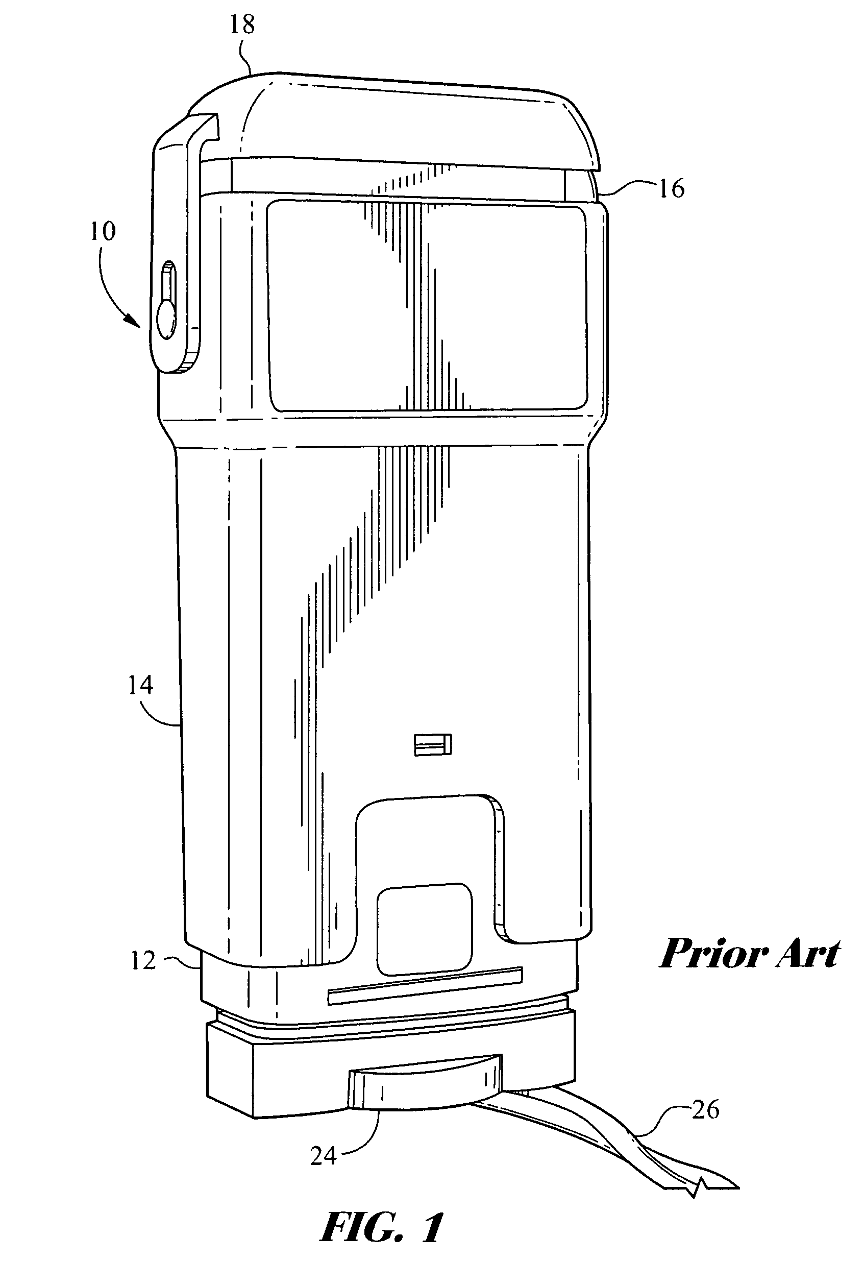
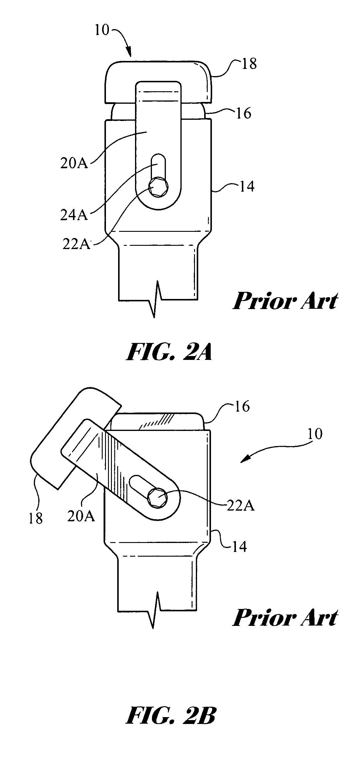
Though the portable strobe light may be useful in military operations, its functionality is limited by the use of moveable mechanical parts.
Maneuvering the mechanical filters may be hindered over time as the portable strobe light is exposed to the weather, dust, dirt and grime.
In addition, the moving parts are subject to damage or breaking when exposed to ongoing wear and tear.

Method used


Image

  • Distress marker system
  • Distress marker system
  • Distress marker system

Examples


Embodiment Construction

[0025]One or more embodiments of the present invention are disclosed herein. The embodiments are merely exemplary of the invention that may be embodied in various and alternative forms. It is noted that the various views, features, elements, and dimensions of the disclosed exemplary embodiments are not necessarily to scale, and may be enlarged, rotated, exaggerated, minimized, or sectionalized for clarity. Thus, specific structural and functional details, dimensions, shapes, or configurations disclosed herein are not limiting but serve as a basis for teaching a person of ordinary skill in the art the described and claimed features of the one or more embodiments of the present invention.

[0026]When describing or introducing elements, features, embodiments, structure, or variations, the terms “a”, “an”, “the”, “it”, and “said” as used herein and in the following claims, means or connotes the singular or plural. Certain terminology is utilized herein for purposes of providing one or mor...


PUM


Abstract

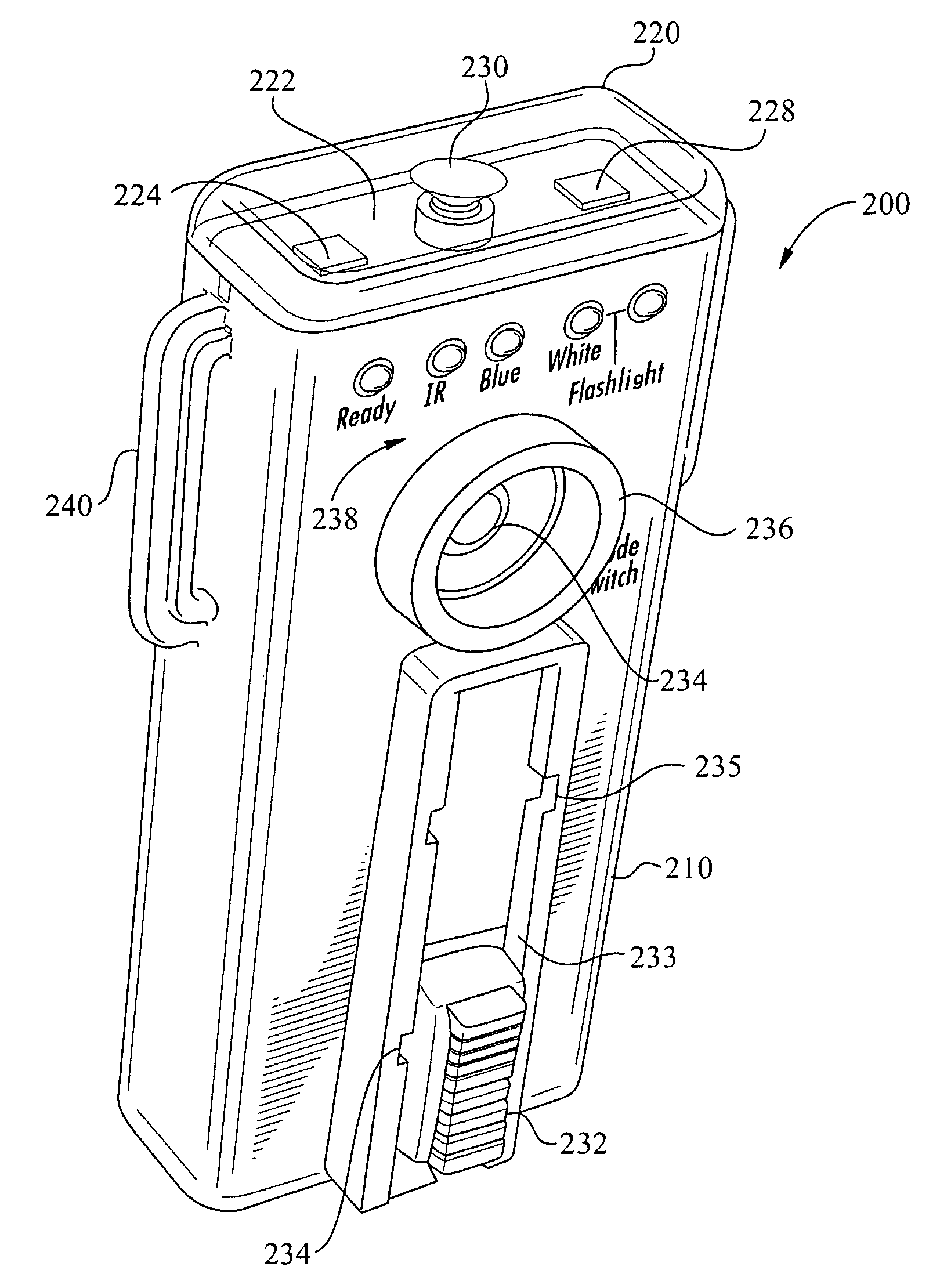
A portable distress light including a plurality of light emitting diodes and a light mode switch to power the diodes so as to provide a flashing white light, a flashing infrared light, a flashing blue light and a steady white light. Status indicators are included on the device to correspondingly identify the operative mode selected. The light emitting diodes include top-emitting diodes and side-emitting diodes that are arranged on a printed circuit board in a variety of configurations to provide an optimum light pattern. Exemplary configurations include positioning the light emitting diodes into a triangular pattern, and a square or rectangular pattern. The distress device further includes a variety of reflectors that are disposed over the light emitting diodes to provide a horizontally dispersed light pattern. An operating circuit provides the benefit of a delay period between mode selections. An alternative embodiment provides a distress light including a cylindrically-shaped form having a top dome attached to a cylindrical body.

Description

FIELD OF INVENTION[0001]The present invention relates to lighting devices, and more particularly, to a portable distress signaling device including multiple light emitting diodes (LED's) that are selectively operated by electronic circuitry to provide visual aid in search and rescue operations on land and at sea for both military and civilian operations.BACKGROUND OF THE INVENTION[0002]There are a number of distress signaling devices that are readily available to imperiled individuals who may be lost at sea or on land as a means of summoning search and rescue operations. The vast oceanic environment and large global landscape makes it extremely difficult to locate one or more individuals who may be lost. Search operations are frequently conducted by marine vessels, aircrafts, and land vehicles in an effort to cover a larger search area. Search teams often face difficult challenges and a variety of hurdles as they undergo their searching efforts. For example, the difficulty of findin...

Claims


Application Information

Patent Timeline
Patent Type & Authority Patents(United States)
IPC IPC(8): F21L4/02
CPCG08B5/002
Inventor SUNSHINE, MORTON
Owner SUNSHINE MORTON
Learn More