
Automated transport device for NMR measuring samples, cryo-magnetic system with automated transport device, transport container for an automated transport device and method for conveying an NMR measuring sample

a technology of automated transport and nmr, which is applied in the direction of measurement devices, instruments, and acoustic wave reradiation. it can solve the problems of expensive transport containers, awkward auxiliary means of this type, and inability to adapt to the coupling of expensive equipmen

Active Publication Date: 2012-07-10
BRUKER SWITZERLAND AG
View PDF14 Cites 25 Cited by
  • Summary
  • Abstract
  • Description
  • Claims
  • Application Information

AI Technical Summary

Benefits of technology

The solution provides a compact, cost-effective, and reliable transport method that minimizes vibration transfer and jamming, enabling efficient and safe transport of NMR samples to the upper end of the RT tube without the need for auxiliary access equipment, ensuring operational safety and convenience.

Problems solved by technology

The above-described transport devices are disadvantageous in that the user must access the height range of the upper end of the RT tube in order to supply the automated device with objects to be transported (and in [3] to supply the cassettes or in [5] to change the carousel cassette), which necessitates auxiliary means such as ladders, stairs or even scaffoldings for larger magnets.
Auxiliary means of this type, however, are awkward and some of them are very expensive.
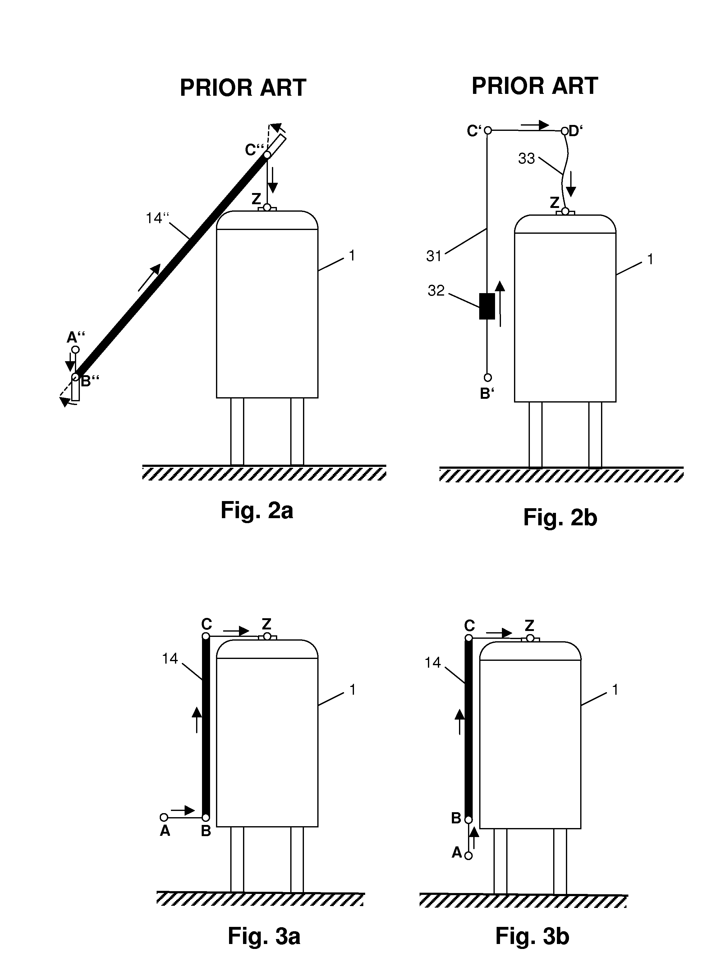
The transport device of [2] is disadvantageous in that, for conveying the object to be transported in a horizontal and vertical direction, an expensive transport container 32 with expensive coupling adaptation is required for receiving the transport container on the horizontal and vertical linear axis.
Local adjustment of the linear axis length 31 cannot be economically performed owing to complex seals, the tools that are required etc., for which reason any re-mounting necessitates complex work preparations and customer-specific material procurement.
The transport device disclosed in [2] is self-supporting (not shown in FIG. 2) and highly massive.
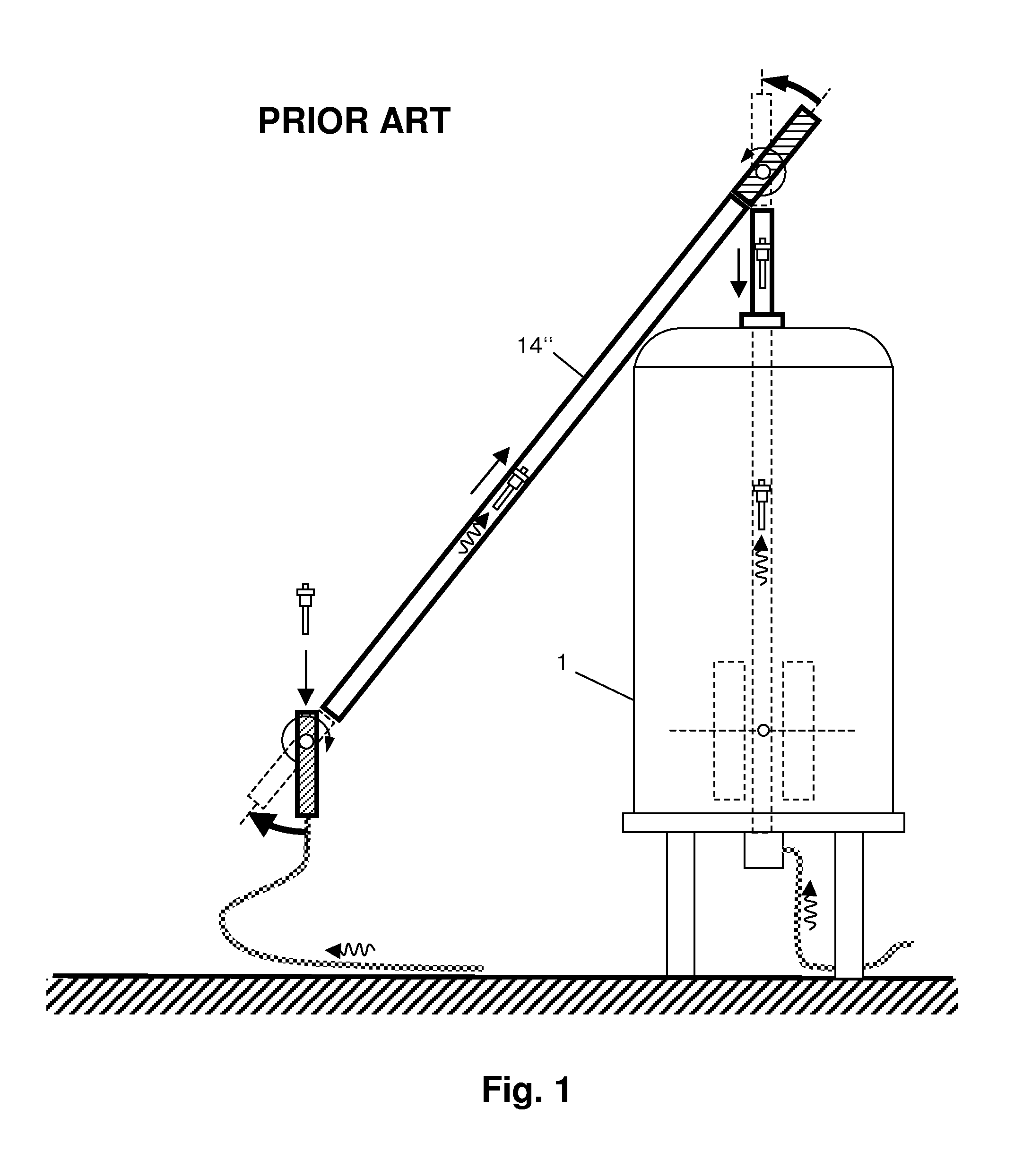
The transport device of [1] is disadvantageous in that the object to be transported and thereby the highly sensitive samples contained therein are rotated out of the vertical axis due to the position of the inclined tube 14″.

Method used


Image

  • Automated transport device for NMR measuring samples, cryo-magnetic system with automated transport device, transport container for an automated transport device and method for conveying an NMR measuring sample
  • Automated transport device for NMR measuring samples, cryo-magnetic system with automated transport device, transport container for an automated transport device and method for conveying an NMR measuring sample
  • Automated transport device for NMR measuring samples, cryo-magnetic system with automated transport device, transport container for an automated transport device and method for conveying an NMR measuring sample

Examples


Embodiment Construction

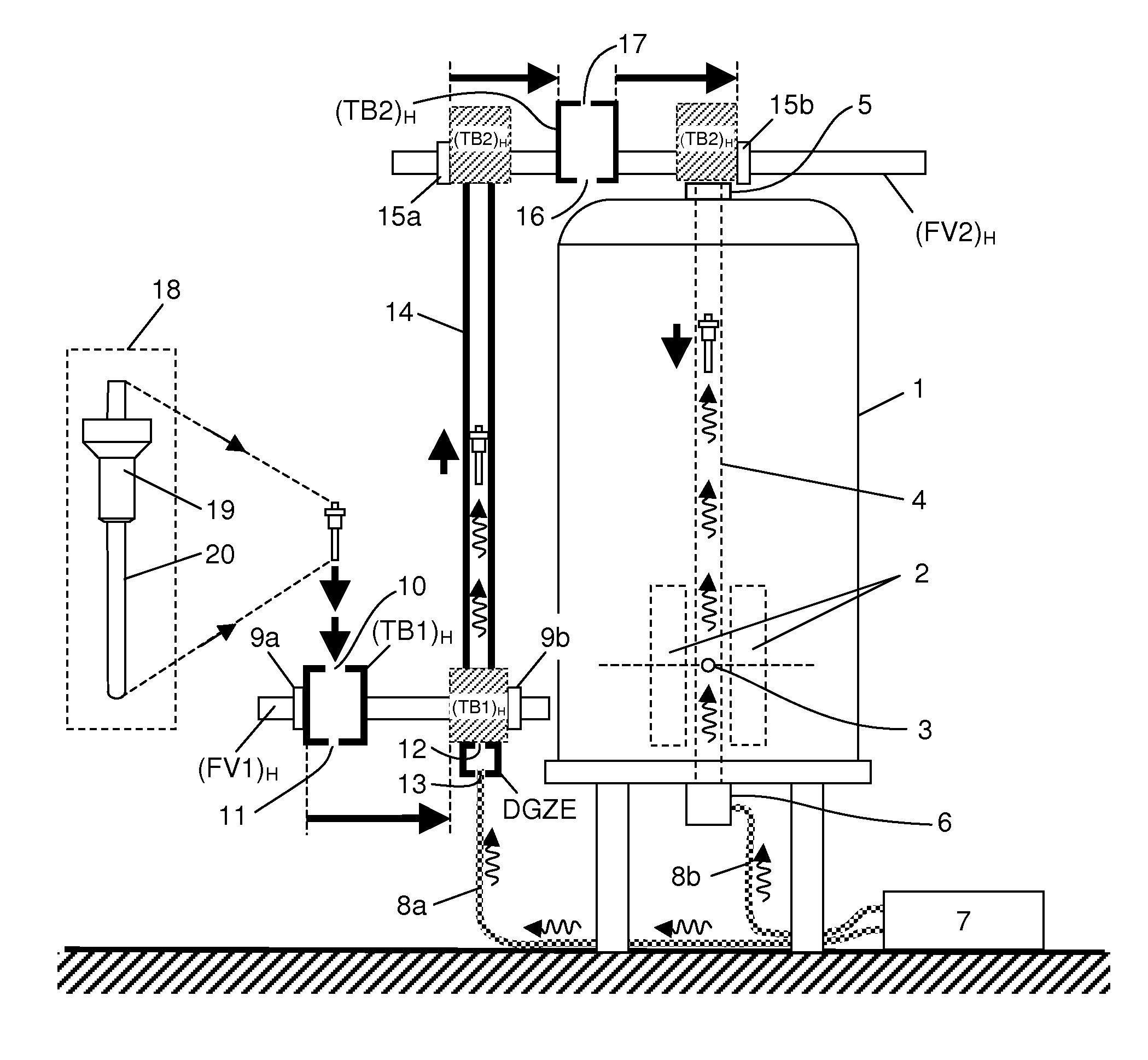
[0085]In the inventive automatic transport device, an object to be transported 18 comprising a sample tube 20 in a sample holder 19 is conveyed from an input point A (FIG. 3a, b), which is easily accessible to the user, to a supply point Z that is disposed above a continuous, vertically extending bore (RT tube 4) of a cryostat 1. The object to be transported is conveyed in three transport sections in each case either horizontally (from the input point A to a first transfer point B and from a second transfer point C to the supply point Z) or vertically (from the first transfer point B to the second transfer point C). The vertical transport is performed by means of a transport tube 14 within which the object to be transported 18 is pneumatically conveyed.

[0086]The transport tube 14 bridges the height difference between the first transfer point B and the second transfer point C next to the upper end of the RT tube 4 in an elegant, economical and extremely flexible fashion, since it can...


PUM


Abstract

A transport device for conveying an object to be transported (18) between an input point (A) and a supply point (Z), where the object to be transported (18) can be supplied to an RT tube (4) of a cryostat (1), wherein the input point (A) is both horizontally and also vertically spaced apart from the supply point (Z), wherein a transport tube (14) is provided for pneumatically conveying the object to be transported within the transport tube (14) from a first transfer point (B) to a second transfer point (C), is characterized in that the transport tube (14) is vertically arranged, a first transport container (TB1) and a second transport container (TB2) are provided for receiving the object to be transported (18), a first transfer device is disposed between the input point (A) and the first transfer point (B), and a second transfer device is provided between the second transfer point (C) and the supply point (Z).

Description

[0001]This application claims Paris Convention priority of DE 10 2008 063 703.3 filed Dec. 19, 2008 the complete disclosure of which is hereby incorporated by reference.BACKGROUND OF THE INVENTION[0002]The invention concerns a transport device for conveying an object to be transported between an input point where the object to be transported can be inserted into and removed from the transport device, and a supply point where the object to be transported can be supplied to an RT tube of a cryostat, wherein the object to be transported comprises an NMR measuring sample and a sample holder, wherein the input point is both horizontally and also vertically spaced apart from the supply point, and wherein a transport tube is provided for pneumatically conveying the object to be transported within the transport tube from a first transfer point at the lower end of the transport tube to a second transfer point at the upper end of the transport tube.[0003]A device of this type is disclosed in ...

Claims


Application Information

Patent Timeline
Patent Type & Authority Patents(United States)
IPC IPC(8): G01V3/00
CPCG01R33/307
Inventor DE VRIES, JONATHANBAUMANN, DANIEL GUYSCHETT, OSKARMAAS, WERNER
Owner BRUKER SWITZERLAND AG
Learn More