Image forming apparatus

a technology of image forming and forming rollers, applied in the direction of electrographic process apparatus, instruments, optics, etc., can solve the problems of deterioration of image quality such as fog and smear, and the toner charge on the development roller becomes unstable, so as to suppress such deterioration of image quality

Inactive Publication Date: 2012-07-03
OKI DATA CORP
View PDF6 Cites 0 Cited by
  • Summary
  • Abstract
  • Description
  • Claims
  • Application Information

AI Technical Summary

Benefits of technology

[0008]An object of the invention is to suppress such deterioration of image quality due to environmental conditions.

Problems solved by technology

In a high-temperature and high-humidity environment, the development roller may absorb moisture thereby increasing its electrical conductivity and thus resulting in charge leakage from the toner.
Hence, the toner charge on the development roller becomes unstable.
For this reason, there is a problem that deterioration of image quality such as fog and smear occurs depending on environmental conditions such as temperature and humidity.

Method used


Image

  • Image forming apparatus
  • Image forming apparatus
  • Image forming apparatus

Examples


first embodiment

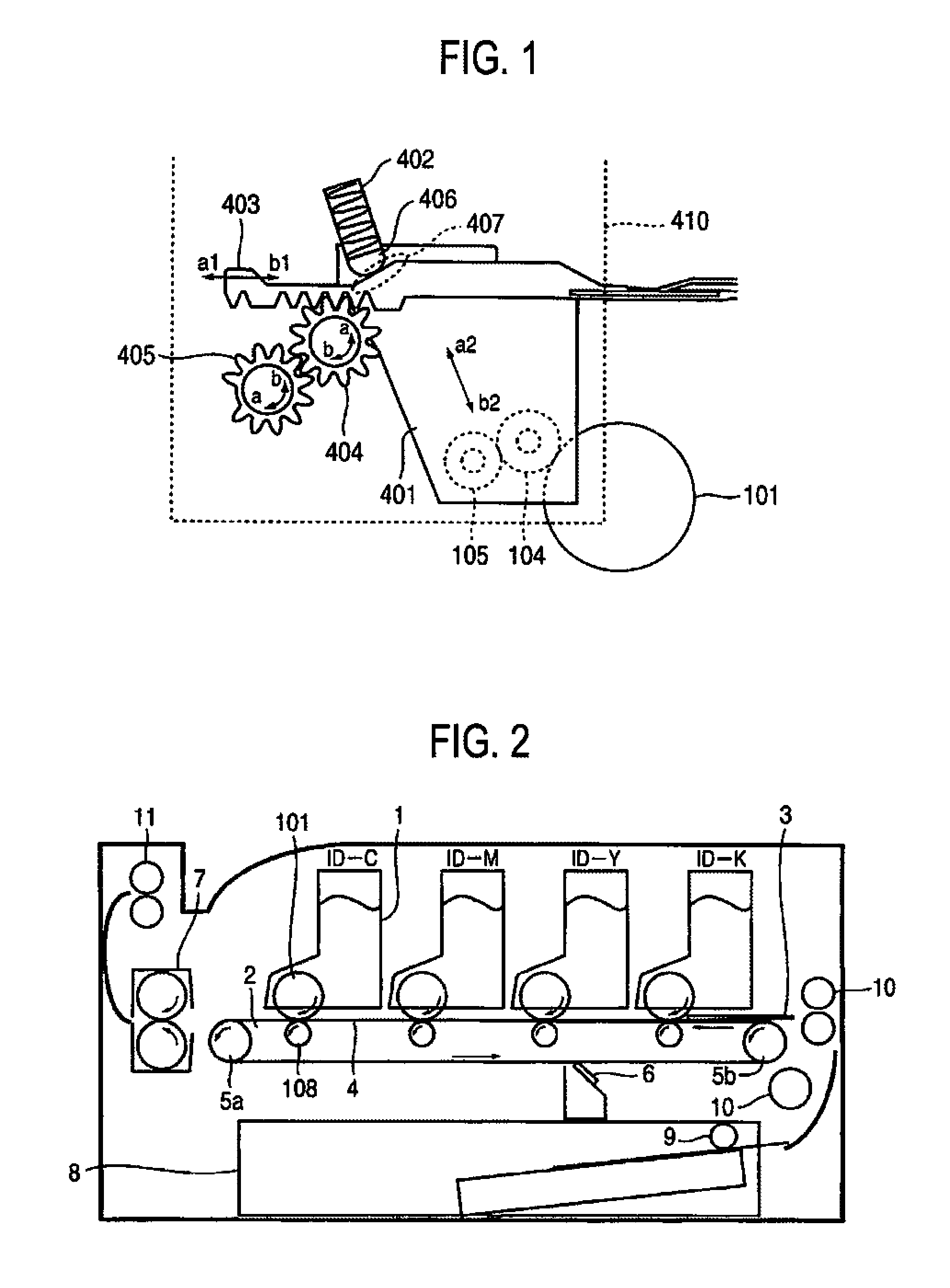
[0027]FIG. 2 is a schematic diagram of an image forming apparatus of the first embodiment. In the description of this embodiment, the image forming apparatus is a color printer of an electrophotographic type.

[0028]In FIG. 2, multiple image drums 1 are provided in the image forming apparatus. In this embodiment, image drums ID-K, ID-Y, ID-M, and ID-C are arranged in this order from upstream at substantially regular intervals, and correspond to toners of color black, yellow, magenta, and cyan, which serve as developers. These image drums 1 have the same structure. Note that, the structure of image drums 1 is described later.

[0029]Image transfer belt unit 2 includes image transfer members 108 such as image transfer rollers, image transfer belt 4 serving as an image transfer member, and conveying rollers 5a and 5b configured to drive image transfer belt 4. Image transfer belt unit 2 is configured to transfer toner images developed on image drums 1 onto recording medium 3.

[0030]Image tra...

second embodiment

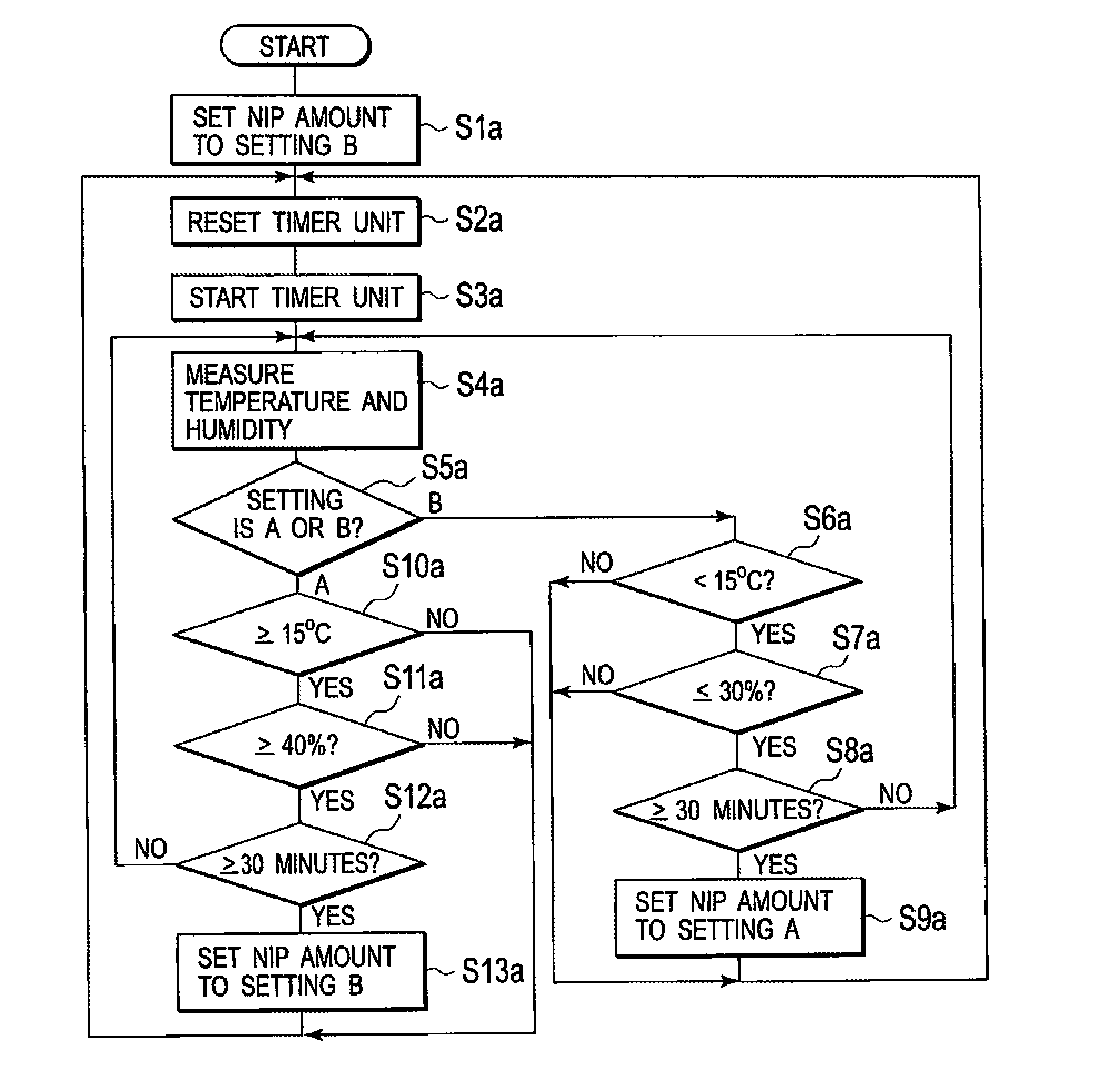
[0108]An image forming apparatus of a second embodiment has a configuration in which the nip amount between development roller 104 and photosensitive drum 101 can be varied on the basis of printed image density, as well as the environment around the image forming unit.

[0109]A control system of the image forming apparatus of the second embodiment is described with reference to FIG. 3 and FIG. 12.

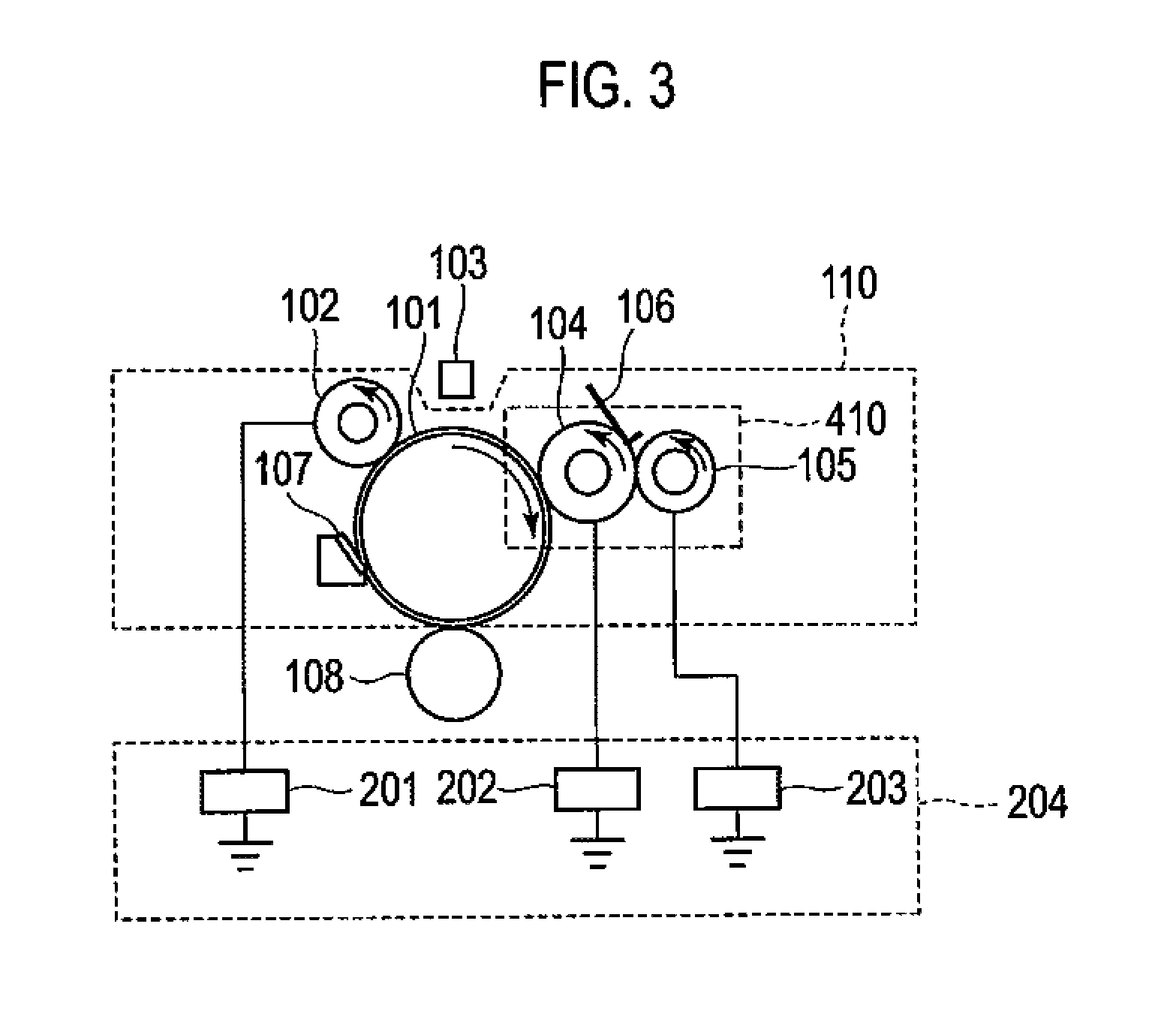
[0110]Note that the image forming apparatus, the image forming unit, and the development roller pressure changing unit of this embodiment are the same as the image forming apparatus shown in FIG. 2, the image forming unit shown in FIG. 3, and the development roller pressure changing unit shown in FIG. 1, FIG. 5, and FIG. 6 described in the first embodiment. Therefore, these components are denoted by the same reference numerals, and description thereof is omitted.

[0111]As shown in FIG. 12, the image forming apparatus includes printer controller 301, interface unit 303, image signal processor 3...


PUM


Abstract

An image forming apparatus includes: an image carrier on which an electrostatic latent image is formed; a developer carrier being in contact with the image carrier and configured to develop the electrostatic latent image on the image carrier with a developer; a temperature humidity measurement unit configured to measure the temperature and humidity around the developer carrier; a pressure changing mechanism configured to change a pressure of a contact between the image carrier and the developer carrier; and a pressure controller operable to change, based on the temperature and humidity measured by the temperature humidity measurement unit, the pressure by controlling the pressure changing mechanism.

Description

CROSS REFERENCE TO RELATED APPLICATIONS[0001]This application claims priority based on 35 USC 119 from prior Japanese Patent Application No. P2009-124637 filed on May 22, 2009, entitled “Image Forming Apparatus”, the entire contents of which are incorporated herein by reference.BACKGROUND OF THE INVENTION[0002]1. Field of the Invention[0003]The invention relates to an image forming apparatus such as a printer or a copier of an electrophotographic type.[0004]2. Description of the Related Art[0005]Conventional image forming apparatus operate as follows. Specifically, an electrostatic latent image is formed on a surface of a photosensitive drum uniformly charged by a changing apparatus, by exposing the surface of the photosensitive drum to light from an exposure apparatus. The electrostatic latent image is developed with a development roller of a developing apparatus being in contact with the photosensitive drum to thereby form a toner image on the photosensitive drum. Thereafter, the ...

Claims


Application Information

Patent Timeline
Patent Type & Authority Patents(United States)
IPC IPC(8): G03G15/06
CPCG03G15/0813G03G21/203
Inventor YAMANE, TSUTOMU
Owner OKI DATA CORP
Why Eureka
Try Eureka