3D image special effects apparatus and a method for creating 3D image special effects

a special effects apparatus and 3d image technology, applied in the field of special effects apparatus, can solve the problem of insufficient consideration of the differences between the parallaxes of small regions, and achieve the effect of suppressing the deterioration of image quality

Active Publication Date: 2013-08-20
PANASONIC CORP
View PDF4 Cites 3 Cited by
  • Summary
  • Abstract
  • Description
  • Claims
  • Application Information

AI Technical Summary

Benefits of technology

[0010]In view of the above problem, a 3D image special effects apparatus that can further suppress a deterioration of the image quality of a 3D image due to special effects in comparison with the conventional apparatuses is provided.
[0017]Another aspect provides a method for creating 3D image special effects in which special effects are created on a 3D image including a first image and a second image having disparity. The method for creating 3D image special effects includes: receiving an input of a specified range of the first image on which the special effects are created; dividing the specified range into a plurality of first image blocks; creating the special effects on each of the plurality of first image blocks; determining an image from the second image which corresponds to an image of the each of the plurality of the first image blocks, and deriving a parallax vector which represents a directionality and a magnitude of parallax between the first image blocks and the corresponding image; determining a plurality of second image blocks on the second image in accordance with the parallax vector, the second image blocks corresponding to the plurality of the first image blocks; and creating the special effects on the determined plurality of second image blocks.
[0018]The 3D image special effects apparatus according to the one aspect can further suppress the deterioration in image quality of a 3D image due to special effects in comparison with the conventional apparatuses.

Problems solved by technology

However, in the conventional 3D image special effects apparatuses, in a case where the region to be subjected to special effects is composed of a plurality of small regions each of which has a parallax of different direction and size with each other, the difference among the parallaxes of the small regions is not sufficiently taken into consideration.

Method used


Image

  • 3D image special effects apparatus and a method for creating 3D image special effects
  • 3D image special effects apparatus and a method for creating 3D image special effects
  • 3D image special effects apparatus and a method for creating 3D image special effects

Examples


first embodiment

1. Principle of 3D Image

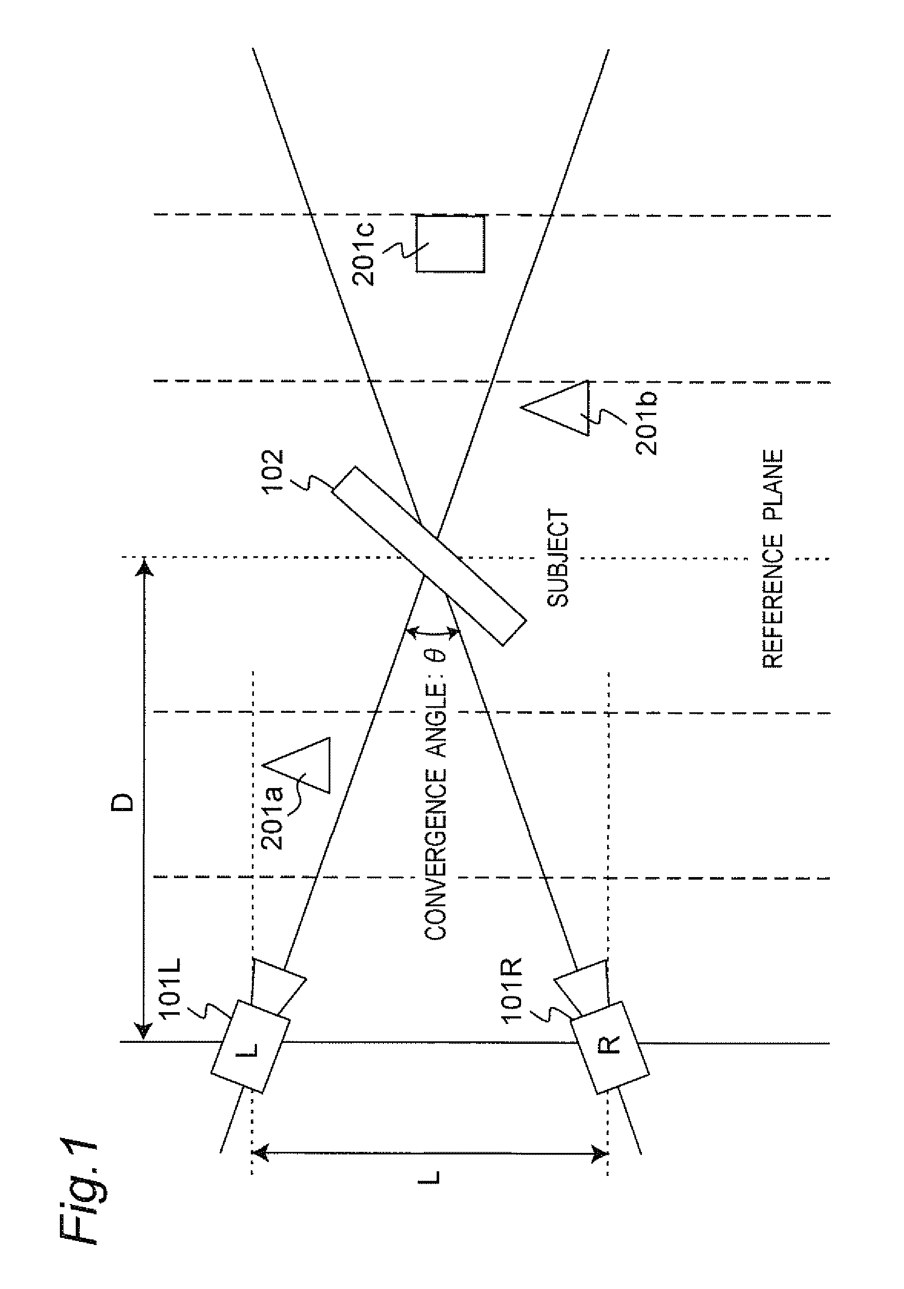
[0040]FIG. 1 is a schematic diagram illustrating camera setting used for shooting 3D images. Parallax between human's left and right eyes is simulated by an installation interval L between a left-eye camera 101L and a right-eye camera 101R, and a convergence angle θ of the left-eye and right-eye cameras 101L and the 101R. The convergence angle θ is an angle between optical axes of the left-eye and right-eye cameras 101L and 101R.

[0041]The average interval between human's (adult) right and left eyes is 65 mm. Therefore, the installation interval L is generally 65 mm. Distance D from the left-eye and right-eye video cameras 101L and 101R to a reference plane is determined in accordance with the installation interval L and the convergence angle θ.

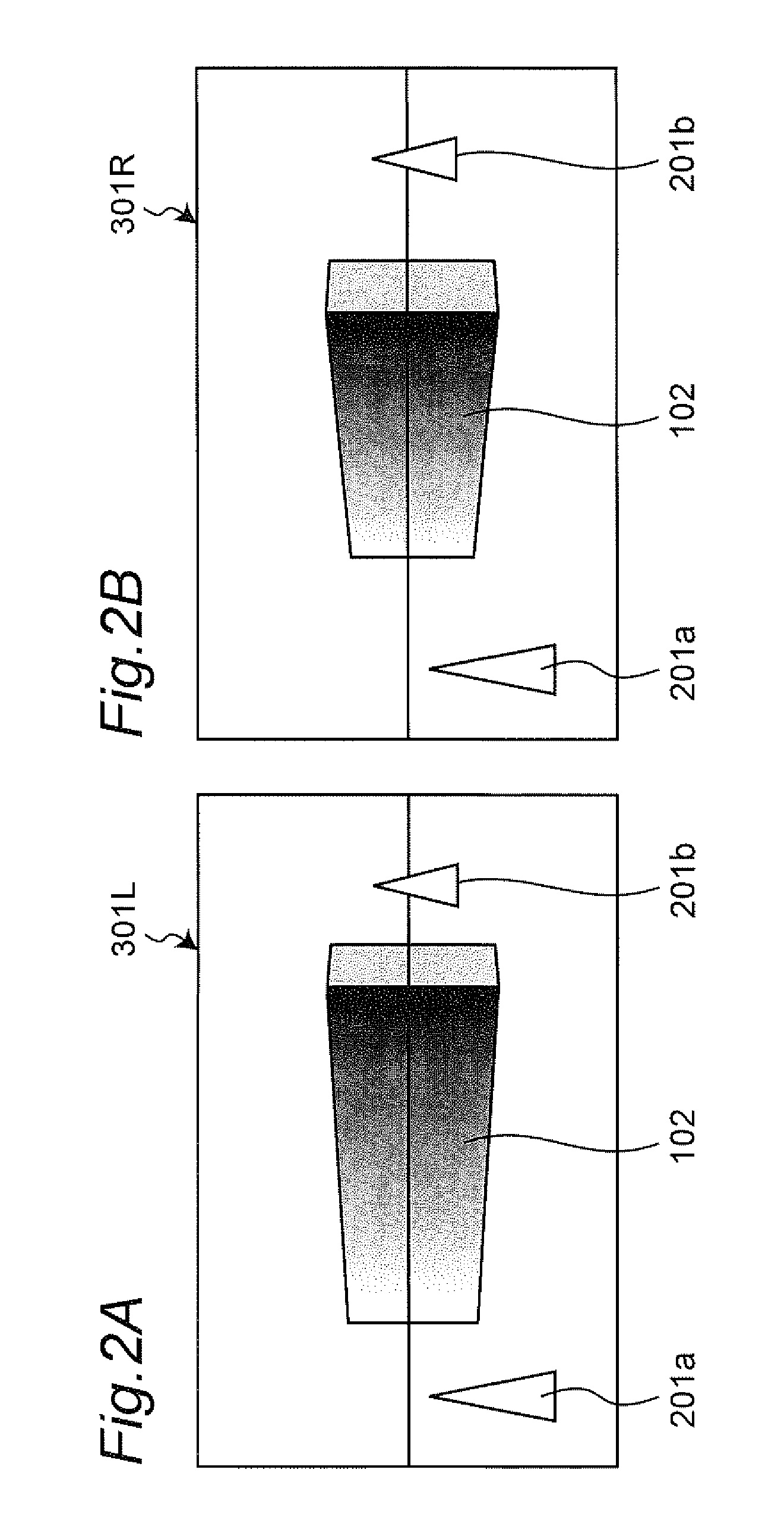
[0042]As to a subject 102 on the reference plane, a parallax between a left-eye image and a right-eye image of a 3D image becomes zero. As the subject separates farther from the reference plane, the magnitude of its par...

second embodiment

[0080]As a second embodiment, the special effects apparatus that partially adjusts the contrast of a 3D image as special effects is described. Since a configuration of the special effects apparatus according to the second embodiment may substantially be the same as that of the first embodiment except for the content of the special effects processing performed by the first and second special effects processing units (17a and 21c), the description thereof is arbitrarily omitted.

[0081]Also on a 3D image, there may be a case where the contrast of a specific range should be adjusted. For this reason, the specified range is further divided into a plurality of blocks, for example, and the contrast adjusting process is executed to pixels in the respective blocks. As a result, adjustment such that only a face part is made to be bright is enabled, for example, on an image of a human whose face part is darkened due to backlighting.

[0082]Conventionally, in order that the contrast adjusting proc...

second embodiments

Summary for First and Second Embodiments

[0091]In the special effects apparatus according to the first and second embodiments, a range of one image composing a 3D image on which special effects are created is used as a reference, and a range of the other image on which the special effects are created can be automatically determined with disparity on the original 3D image being retained. For this reason, the natural 3D special effects that do not deteriorate a stereoscopic effect of the original 3D image can be provided. Further, only when the range on which the special effects are created is specified on one image, the process can be automatically executed on the other image. For this reason, the workload for editing can be reduced.

[0092]The mosaic processing and the contrast adjusting process are mainly described as the examples of the special effects, but the special effects include a digital removal process, and a calibration process for differences between left-eye and right-eye ...


PUM


Abstract

A 3D image special effects apparatus for creating special effects on a 3D image including a first image and a second image having disparity. The 3D image special effects apparatus includes: a range specification receiving unit capable of receiving an input of a specified range of the first image on which the special effects are created; a first block division unit capable of dividing the specified range into a plurality of first image blocks; a first special effects unit capable of creating the special effects on each of the plurality of the first image blocks; a block matching unit capable of determining an image from the second image which corresponds to an image of the each of the plurality of the first image blocks, and deriving a parallax vector which represents a directionality and a magnitude of parallax between the first image blocks and the corresponding image; a second block division unit capable of determining a plurality of second image blocks on the second image in accordance with the parallax vector, the second image blocks corresponding to the plurality of first image blocks; and a second special effects unit capable of creating the special effects on the determined plurality of second image blocks.

Description

BACKGROUND[0001]1. Technical Field[0002]The technical field relates to a special effects apparatus that gives special effects to an image, and, more particularly to a 3D image special effects apparatus that gives special effects to a 3D image.[0003]2. Related Art[0004]In recent years, attention is paid to techniques relating to 3D images. 3D images are images that can be viewed stereoscopically, and for example, stereo images that are generated based on an image for the left eye and an image for the right eye captured synchronously (hereinafter, also referred to as “left-eye image” and “right-eye images”). Normally, the left-eye image and the right-eye image include disparity corresponding to the human's binocular disparity.[0005]Actually, various apparatuses for displaying the 3D imagery and various methods for showing the 3D imagery to a viewer have already been proposed. They are based on the basic principle such that a viewer can be allowed to recognize a sense of depth of image...

Claims


Application Information

Patent Timeline
Patent Type & Authority Patents(United States)
IPC IPC(8): G06T15/00
CPCG03B35/08G03B35/20G06T7/0022H04N5/262H04N13/0007G06T2207/10021G06T2207/20021G06T7/97H04N13/106
Inventor SAITO, HIROSHI
Owner PANASONIC CORP
Why Eureka
Try Eureka