Switching amplifier using flyback transformer

a technology of switching amplifier and flyback transformer, which is applied in the direction of amplifiers, amplifiers with modulator/demodulator, amplifiers, etc., can solve the problems of inefficient power usage, excessive losses, and short dead times, and achieve the effect of adding more outputs easily and economically

Inactive Publication Date: 2012-07-03
HSIEH WEN HSIUNG
View PDF23 Cites 15 Cited by
  • Summary
  • Abstract
  • Description
  • Claims
  • Application Information

AI Technical Summary

Benefits of technology

[0013]The present invention discloses a switching amplifier that produces one or more than one linearly amplified replicas of an input signal, is highly efficient, and does not have the “dead time” problem related to class D amplifiers.
[0019]From the switching amplifier in accordance with the present invention, one aspect of the present invention provides a switching amplifier that is highly efficient and without the “dead time” problem related to the class D amplifiers.
[0022]From the switching amplifiers in accordance with the present invention, yet another aspect of the present invention provides a switching amplifier for obtaining a plurality of different linearly amplified replicas of the input signal efficiently, and adds more outputs easily and economically.

Problems solved by technology

In general, class A amplifiers produce a linearly amplified replica of an input signal, but are inefficient in terms of power usage because the amplifying elements are always biased and conducting, even if there is no input.
This arrangement gives excellent efficiency, but can suffer from the drawback that there is a small mismatch in the cross-over region—at the “joins” between the two halves of the signal, as one output device has to take over supplying power exactly as the other finishes.
However, one significant challenge for a driver circuit in class D amplifiers is keeping dead times as short as possible.
Dead times need to be as short as possible to maintain an accurate low-distortion output signal, but dead times that are too short cause the MOSFET that is switching on to start conducting before the MOSFET that is switching off has stopped conducting.
Driver failures that allow shoot-through result in excessive losses and sometimes catastrophic failure of the MOSFETs.
Therefore, the main disadvantage of a class D amplifier is having the “dead time” problem to cause the distortion of the output signal.
In summary, class A amplifiers produce a linearly amplified replica of an input signal, but are inefficient in terms of power usage.
The push-pull class B amplifiers provide excellent efficiency (compared to class A amplifiers), but introduce crossover distortion.
Class D amplifiers are most efficient compared to class A and class B amplifiers, but there is one significant problem for MOSFET driver circuits in class D amplifiers: the “dead time” that cause the distortion of the output signal.

Method used


Image

  • Switching amplifier using flyback transformer
  • Switching amplifier using flyback transformer
  • Switching amplifier using flyback transformer

Examples


Embodiment Construction

[0037]The detailed description set forth below in connection with the appended drawings is intended as a description of presently preferred embodiments of the invention and is not intended to represent the only forms in which the present invention may be constructed and or utilized.

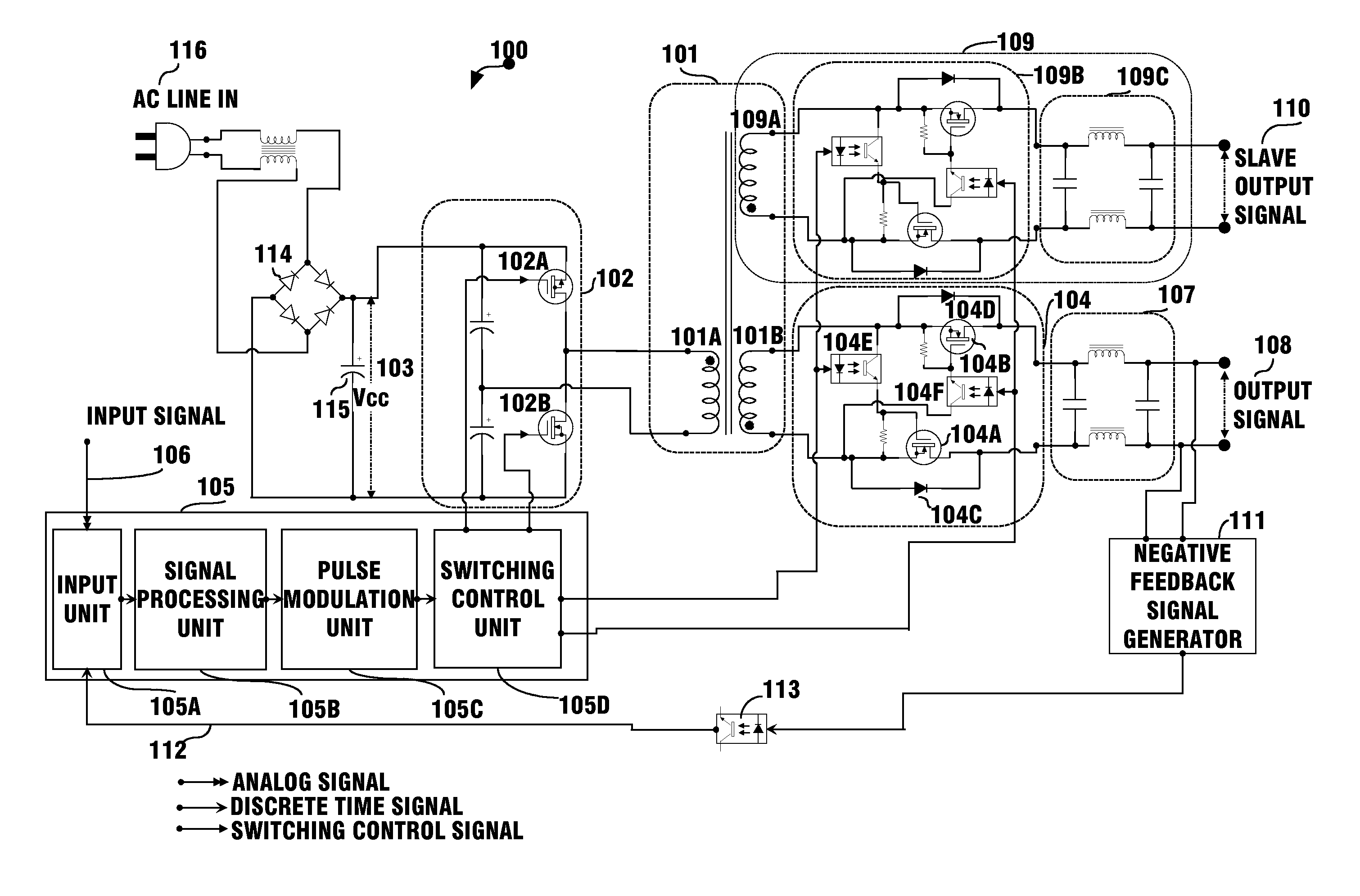
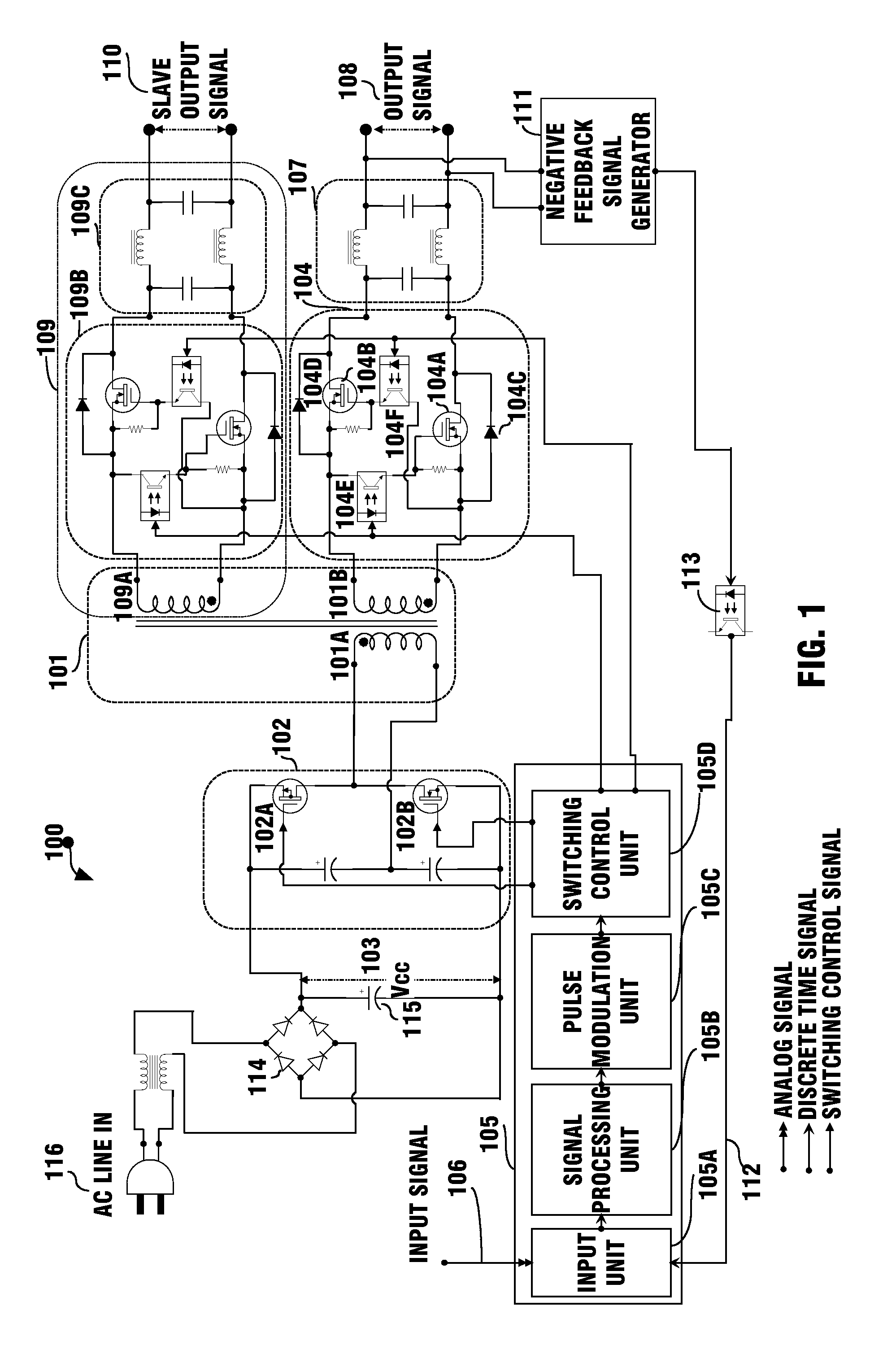
[0038]FIG. 1 is an exemplary block and circuit diagram illustrating an embodiment of a switching amplifier 100 in accordance with the first method of present invention, wherein the switching amplifier 100 having switches 102A and 102B configured as a half bridge topology.

[0039]As illustrated in FIG. 1, the switching amplifier 100 of the present invention for amplifying an input signal 106 having positive and negative polarities is comprised of: a transformer 101 comprising a primary winding 101A and a secondary winding 101B magnetically coupled to the primary winding 101A; a switching unit 102 comprising two switches 102A and 102B configured as a half bridge topology coupled to the primary winding 101A fo...


PUM


Abstract

A switching amplifying method or a switching amplifier for obtaining one or more than one linearly amplified replicas of an input signal, is highly efficient, and does not have the disadvantage of “dead time” problem related to the class D amplifiers. Another aspect of the present invention provides a switching amplifier that is completely off when there is no input signal. Yet another aspect of the present invention provides a switching amplifier for obtaining a plurality of different linearly amplified replicas of the input signal, and adds more slave outputs easily and economically.

Description

BACKGROUND OF THE INVENTION[0001](1) Field of the Invention[0002]This invention is related in general to a power amplifier, and more particularly, to a switching amplifier that can efficiently and linearly amplify an input signal having first and second polarities for obtaining one or more than one low-distortion output signals.[0003](2) Description of the Related Art[0004]Amplifiers are electronic devices which are used for increasing the power of a signal, and are generally categorized into various classes. The popular amplifiers include class A, class B and class D amplifiers. Reference is made to the exemplary U.S. Patents that disclose various types of amplifiers: U.S. Pat. Nos. 7,952,426; 7,816,985; 7,400,191; 7,286,008; 6,922,101; 6,794,932; 6,563,377; 6,356,151; 6,282,747; 5,949,282; 5,805,020; 5,767,740; 5,160,896; 5,115,205; 5,014,016; 4,531,096 and 3,629,616.[0005]In general, class A amplifiers produce a linearly amplified replica of an input signal, but are inefficient i...

Claims


Application Information

Patent Timeline
IPC IPC(8): H03F3/38
CPCH03F1/3205H03F3/2171H03F3/2173H03F3/393H03F2200/273H03F2200/276H03F2200/351H03F2200/537
Inventor HSIEH, WEN-HSIUNG
Owner HSIEH WEN HSIUNG
Why Eureka
Try Eureka