
Model-based control of airpath pressure limits by modulating a turbo charger by-pass valve and a variable-geometry turbine

a technology of variable geometry turbine and airpath pressure limit, which is applied in the direction of electric control, machines/engines, instruments, etc., can solve the problems of intermittent power loss and reduced efficiency of engine components equipped with forced induction components

Active Publication Date: 2012-07-03
GM GLOBAL TECH OPERATIONS LLC
View PDF1 Cites 20 Cited by
  • Summary
  • Abstract
  • Description
  • Claims
  • Application Information

AI Technical Summary

Problems solved by technology

During changes in operating conditions such as changes in engine load and engine r.p.m., engines equipped with forced induction components often experience reduced efficiency and intermittent power loss owing to sudden transient drops in turbine efficiency.

Method used


Image

  • Model-based control of airpath pressure limits by modulating a turbo charger by-pass valve and a variable-geometry turbine
  • Model-based control of airpath pressure limits by modulating a turbo charger by-pass valve and a variable-geometry turbine
  • Model-based control of airpath pressure limits by modulating a turbo charger by-pass valve and a variable-geometry turbine

Examples


Embodiment Construction

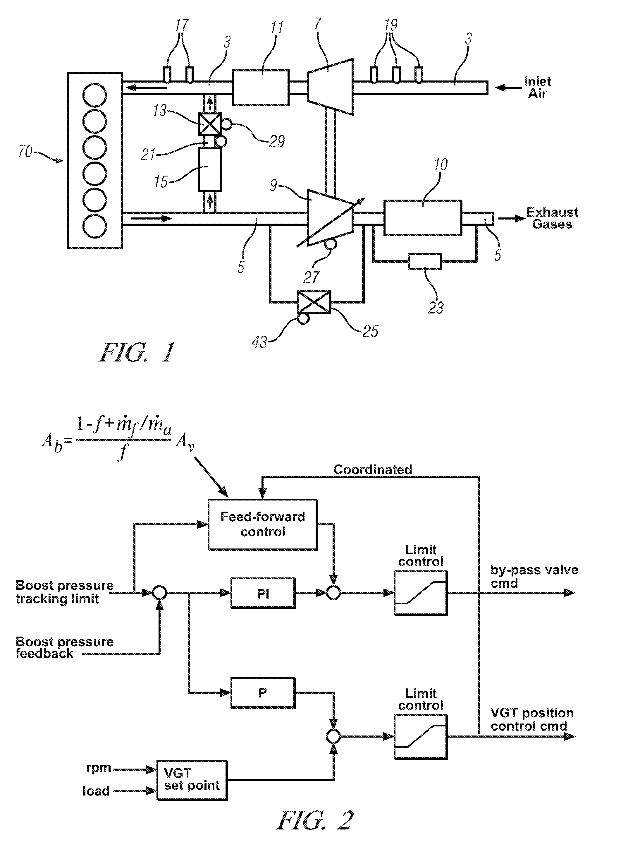
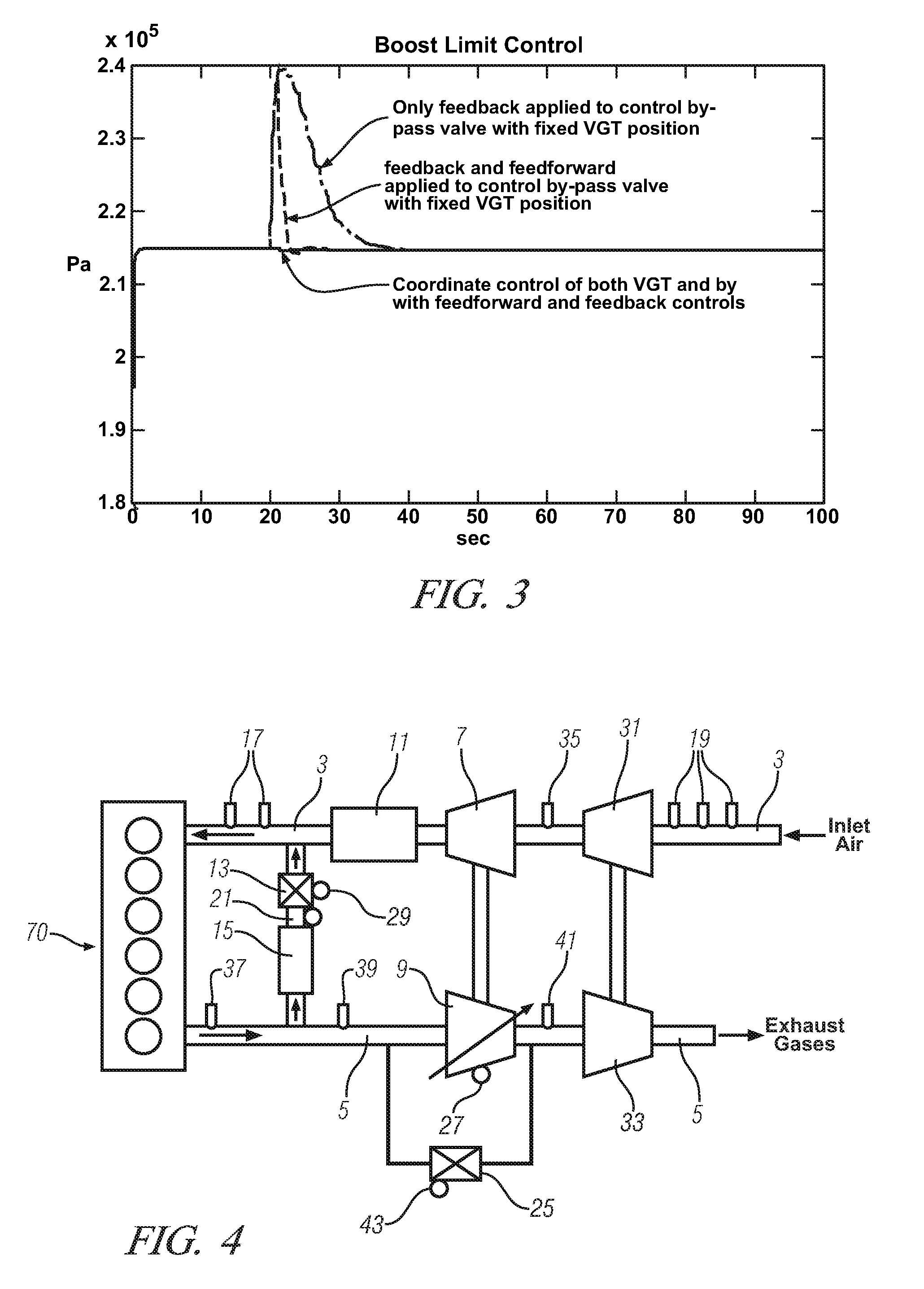
[0014]Referring now to the drawings, which are provided for the purpose of illustrating exemplary embodiments only and not for the purpose of limiting same, FIG. 1 shows a schematic view of a combustion engine 70, and accessories associated with its operation, according to one embodiment of the disclosure. The combustion engine may be either a spark-ignition engine or a compression-ignition engine, and in preferred embodiments is piston-driven. In this FIG. 1 there is shown an air inlet conduit 3 through which ambient air passes on its way to one or more engine cylinders. There is also an exhaust gas conduit 5 through which exhaust gases from the combustion engine 70 are expelled during its normal operation. In some embodiments, a first compressor 7 is provided, to compress the inlet air to increase its density to provide a higher concentration of oxygen in the air fed to the engine. The first compressor 7 may be shaft-driven by a first turbine 9, which may be a variable-geometry tu...


PUM


Abstract

Simultaneous or independent control of a by-pass valve and a variable-geometry forced induction component on a combustion engine is based on operational parameters measured by various sensors provided as inputs to a control module. Sudden loss of power due to low turbine efficiencies is prevented during transitions between operating conditions of engine speed and load. Excessive peak cylinder pressures are also prevented by controlling engine boost pressure to a permitted limit at high engine speed and load.

Description

TECHNICAL FIELD[0001]The present disclosure generally relates to the operation of combustion engines, and more particularly relates to control of air intake charge and exhaust pressures during operation of combustion engines.BACKGROUND[0002]The statements in this section merely provide background information related to the present disclosure and may not constitute prior art.[0003]Modern combustion engines equipped with systems that include forced-induction components such as turbo chargers are typically equipped with control systems for controlling their operation, including their performance characteristics. Such control over engine operation and exhaust gas streams are made largely possible by placement of various types of sensors about the engines, which sensors have outputs that are routed as inputs to a control module(s) which in turn is in operative control with various engine control means to control, inter alia, the pressure of engine exhaust gases and turbo charger boost pr...

Claims


Application Information

Patent Timeline
IPC IPC(8): F02D23/00F02B33/44
CPCF02B37/004F02D41/0007F02D41/1448F02M25/0707F02M25/0727F02M25/0756F02B37/013F02B37/18F02B37/24F02D41/1446Y02T10/144F02M26/48F02M26/05F02M26/23Y02T10/12
Inventor WANG, YUE-YUNLI, XIAOBIN SHARONGAO, HONGXUNHASKARA, IBRAHIM
Owner GM GLOBAL TECH OPERATIONS LLC
Learn More