
System for storage and navigation of application states and interactions

a technology of application state and application state, applied in the field of application state and interaction storage system, can solve the problems of inability to remember the factors that influenced earlier stages of planning, inability to accurately predict the current state of an application,

Active Publication Date: 2012-06-26
ACCENTURE GLOBAL SERVICES LTD
View PDF121 Cites 9 Cited by
  • Summary
  • Abstract
  • Description
  • Claims
  • Application Information

AI Technical Summary

Benefits of technology

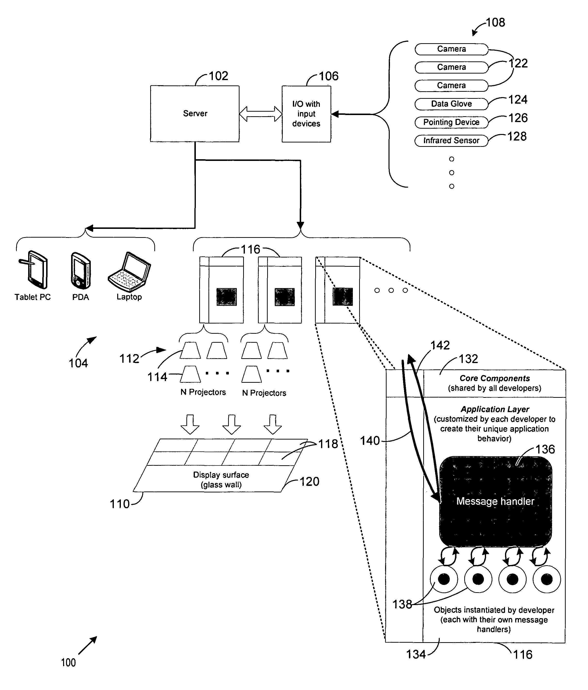
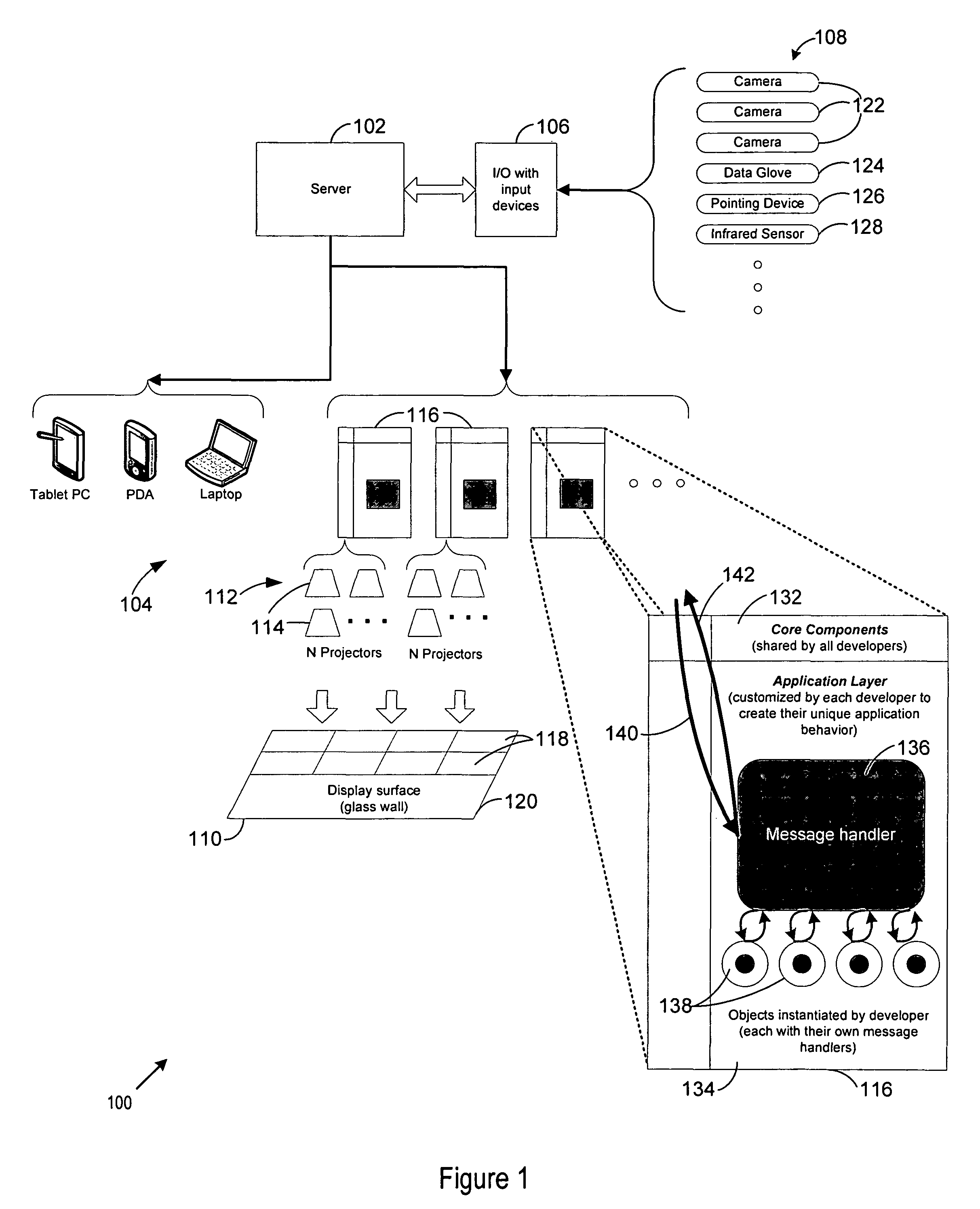
[0018]Given this backdrop of complex planning design and planning leading to complex applications, a navigation system provides an application-independent mechanism that allows operators to walk back through the history of the application. The navigation system thereby allows the operator to better understand (or remember) the actions that were taken in the past and the triggers for those actions. Because the actions determine how the application reached any given state at any given time, the navigation system allows the operator to obtain the insight necessary to understand not only the present state of the application, but also the manner in which the application changed over time, and why. In addition, a display image generated by coordinated display devices may provide an extensive graphical interface for conveying the application history, actions taken on the application, contemporaneous environmental data, or any other data useful for understanding the history of the application.

Problems solved by technology

Groups of people often use complex collaboration and decision support tools, over long periods of time, to perform complex design and planning actions and decisions which drive an application (e.g., a chemical plant process configuration or a complex material distribution chain) to its current state.
The combination of time and complexity can often obscure past actions and decisions, making it difficult to remember the factors that influenced earlier stages in the planning.
Any understanding of how an application arrived at its current state was often limited by individual, often inaccurate, memories, hastily taken notes, and poor documentation.
Accordingly, it was very difficult to unravel the history of the design and planning steps leading to the current state of the application.
For these and other reasons, substantial challenges existed in providing an understanding of how and why decisions were made, who made the decisions, and how those decisions impacted the current state of the application.
These limitations hindered the further development, improvement, and changes to the application as well as attempts to understand how an application arrived at its current state.
The limitations also greatly increased the difficulty of effectively and efficiently introducing new people to development or planning roles for the application.
At the same time, the amount of data underlying the history of the application presents significant display, manipulation, and presentation challenges.
However, the enormous volume of data and the density of inter-connections can make it difficult to easily visualize this information on standard workstations.
While multimedia capabilities can enhance the presentation of information, the small size and limited features of the conventional device make meaningful presentation of the information difficult.
Furthermore, the complexity of the data and the decision making processes necessitate a shared view and collaboration among multiple experts.
Due to constraints with both technology and form factor, such an environment requires a system that can distribute one logical application across multiple computers and display systems that make up the immersive environment.
Adequate systems to provide the necessary capabilities have not been available.
Currently there is no standard architecture, language or protocol for building applications that span multiple and possibly heterogeneous computers, multiple displays, possibly of different form factors, and multiple interaction modalities.
Some commercially available system are typically built using expensive video processors that allow information and graphical data to be displayed on a screen, but not necessarily as one cohesive application.

Method used


Image

  • System for storage and navigation of application states and interactions
  • System for storage and navigation of application states and interactions
  • System for storage and navigation of application states and interactions

Examples


Embodiment Construction

[0050]The elements illustrated in the Figures interoperate as explained in more detail below. Before setting forth the detailed explanation, however, it is noted that all of the discussion below, regardless of the particular implementation being described, is exemplary in nature, rather than limiting. For example, although selected aspects, features, or components of the implementations are depicted as being stored in memories, all or part of systems and methods consistent with the application state navigation system and method may be stored on, distributed across, or read from other machine-readable media, for example, secondary storage devices such as hard disks, floppy disks, and CD-ROMs; a signal received from a network; or other forms of ROM or RAM either currently known or later developed.

[0051]Furthermore, although specific components of the application state navigation system will be described, methods, systems, and articles of manufacture consistent with the application sta...


PUM


Abstract

Complex collaboration or decision support applications perform complex design or planning tasks, often with the input of large groups of people over long periods of time. The combination of time and complexity can often obscure past actions, making it difficult to remember the factors that influenced earlier stages in the planning task. This is especially true if the task involves many people and different people work at different times. The application state navigation system provides an application-independent mechanism that allows operators to walk back through the history of the application in order to better understand (or remember) the application actions that were taken in the past and the triggers for those actions.

Description

PRIORITY CLAIM[0001]This application claims the benefit of priority from U.S. Provisional Patent Application No. 60 / 764,004, filed Jan. 31, 2006, which is incorporated herein by reference.BACKGROUND OF THE INVENTION[0002]1. Copyright Notice[0003]A portion of the disclosure of this patent document contains material which is subject to copyright protection. The copyright owner has no objection to the facsimile reproduction by anyone of the patent document or the patent disclosure, as it appears in the Patent and Trademark Office patent file or records, but otherwise reserves all copyright rights whatsoever.[0004]2. Technical Field[0005]This invention relates to tracking and display of the history of an evolving application. In particular, this invention relates to a system through which an operator may navigate in time through application states, actions taken on the application, and the triggers for those actions to view the application at selected temporal points in the past.[0006]3...

Claims


Application Information

Patent Timeline
Patent Type & Authority Patents(United States)
IPC IPC(8): G06F3/048G06K9/00G06F3/042G05B9/02G06F15/16
CPCG06Q10/10G06F8/20G06F3/04842G06F8/65
Inventor DEMPSKI, KELLY L.HARVEY, BRANDON L.
Owner ACCENTURE GLOBAL SERVICES LTD
Learn More