Imaging of polarization scrambling tissue

a technology of polarization scrambling and imaging tissue, applied in the field of depolarization imaging, can solve the problems of visual impairment, loss of vision, and inability to resolve each scatterer

Inactive Publication Date: 2012-06-26
CARL ZEISS MEDITEC INC
View PDF13 Cites 7 Cited by
  • Summary
  • Abstract
  • Description
  • Claims
  • Application Information

AI Technical Summary

Benefits of technology

[0013]The claims define the present invention and nothing in this section should be taken as a limitation on those claims. Advantageously, embodiments of the present invention overcome the computational complexity and / or expensive detection hardware previously used in the art. The invention provides a means for imaging polarization scrambling tissue (alternatively called depolarization imaging herein) without resolution of Stokes vectors or the Mueller matrix and without the need of additional detection hardware.

Problems solved by technology

Pathology and disease states of the human eye lead to visual impairment and, in the worst case, loss of vision.
Because OCT detection is coherent, depolarization, or polarization scrambling, by biological tissue simply means that the tissue does not present a spatially consistent polarization response across independent neighboring detection cells.
In general, however, it is impractical to resolve each scatterer.
Full resolution of the Mueller or Jones matrix is costly and / or time consuming.
In this case, the cost is in additional hardware.
Additionally, a PS-OCT system is relatively difficult to align and calibrate.

Method used


Image

  • Imaging of polarization scrambling tissue
  • Imaging of polarization scrambling tissue
  • Imaging of polarization scrambling tissue

Examples


Embodiment Construction

[0024]The embodiments, examples and descriptions illustrate the principles of the invention and its practical applications and are not a definition of the invention. Modifications and variations of the invention will be apparent to those skilled in the art. The claims define the scope of the invention and include known equivalents and equivalents unforeseeable at the time of filing of this application.

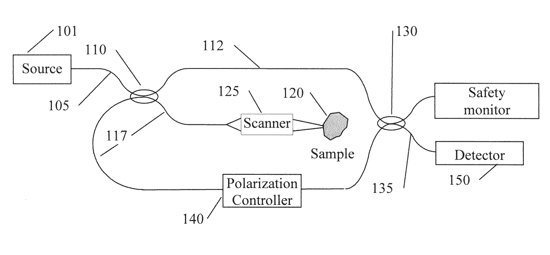
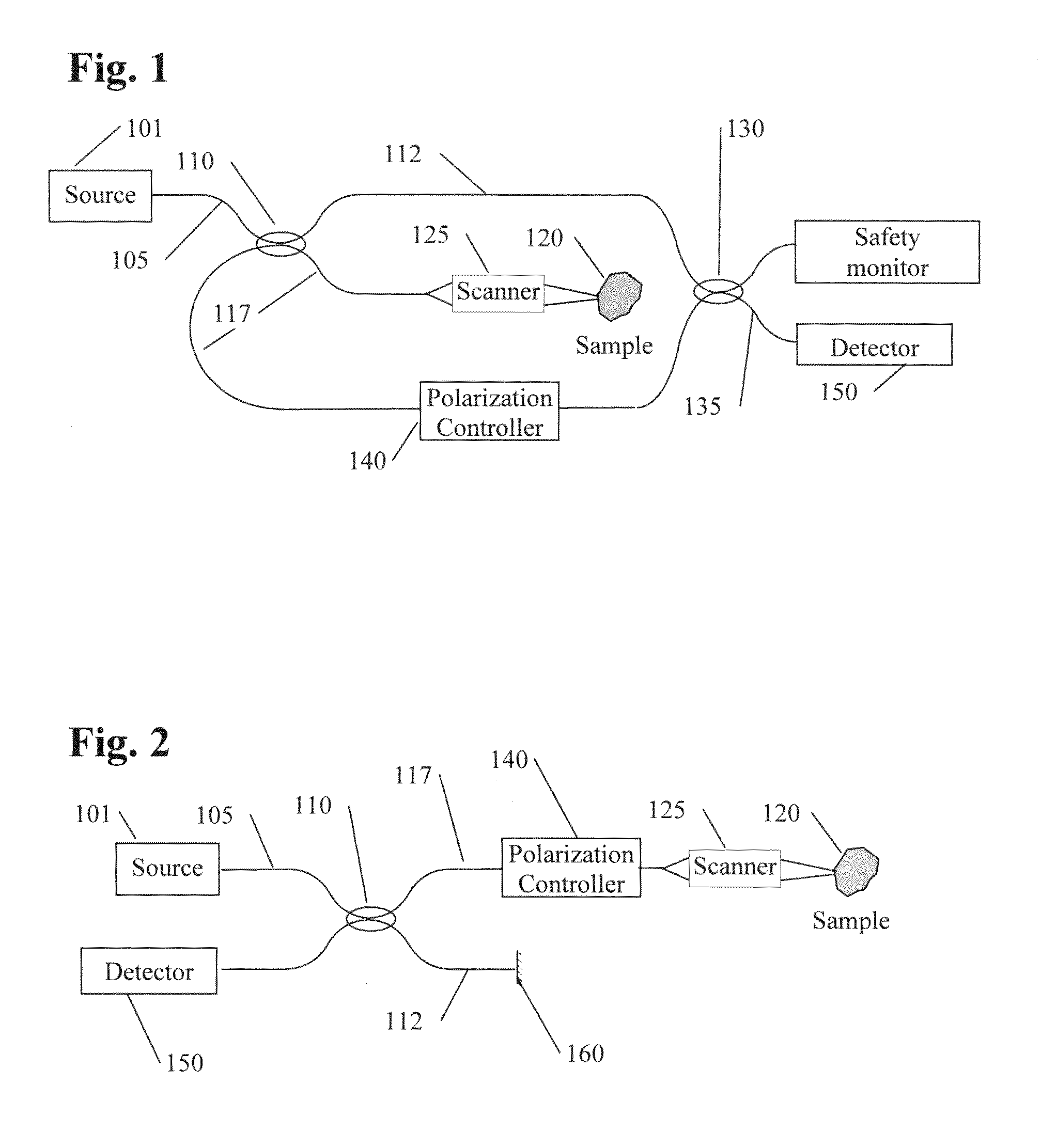
[0025]One embodiment of the invention is an apparatus for computing a tomographic image of a depolarizing tissue. One such apparatus includes an optical coherence tomography (OCT) device comprising of an interferometer like the one depicted in FIG. 1 having a source arm 105, a reference arm 112, a sample arm 117 (here shown in two parts since the splitting coupler 110 and combining coupler 130 are separate and distinct) and a detector arm 135. A source 101, typically a superluminescent diode (SLD), of at least partially spatially coherent light is coupled to the source arm 105. A polar...


PUM


Abstract

The present invention provides for the detection and display of polarization scrambling tissue without resolving the polarization state of the backscattered imaging beam. In one embodiment, we illuminate the tissue using two different polarizations. A first polarization determines a first image of high intensity while the second polarization determines a second image of low intensity. Comparison and combination of the first and second images determines tissue which scrambles the polarization in neighboring detection cells.

Description

PRIORITY INFORMATION[0001]This application claims priority from U.S. Provisional Application Ser. No. 61 / 070,535, filed Mar. 24, 2008, the disclosure of which is incorporated herein by reference.TECHNICAL FIELD[0002]The invention relates to the field of depolarization imaging. In particular, the invention pertains to optical imaging of polarization scrambling scattering tissue. It has particular relevance in optical coherence tomography (OCT).DISCUSSION OF BACKGROUND[0003]Pathology and disease states of the human eye lead to visual impairment and, in the worst case, loss of vision. Optical assessment of the eye's health is preferred because of the non-invasive nature of optical examination techniques. Common eye diseases include glaucoma, age-related macular degeneration, cataracts, retinal detachment, and diabetic retinopathy. Improved optical diagnostic techniques offer hope in quantifying disease progression and in tracking the effectiveness of disease treatments.[0004]Previous w...

Claims


Application Information

Patent Timeline
Patent Type & Authority Patents(United States)
IPC IPC(8): G01J4/00A61B5/00G01B9/02
CPCA61B3/102A61B3/1225
Inventor MEYER, SCOTT A.WEI, XING
Owner CARL ZEISS MEDITEC INC
Why Eureka
Try Eureka