Eureka AIR delivers breakthrough ideas for toughest innovation challenges, trusted by R&D personnel around the world.

System and method to remove artifacts from fingerprint sensor scans

a fingerprint sensor and artifact technology, applied in the field of system and method to remove artifacts from fingerprint sensor scans, can solve the problems of distorted image, inability to achieve normal operation, and misleading finger location stamps

Inactive Publication Date: 2012-06-19
SYNAPTICS INC
View PDF385 Cites 45 Cited by
  • Summary
  • Abstract
  • Description
  • Claims
  • Application Information

AI Technical Summary

Benefits of technology

[0019]This method is particularly useful for creating “intelligent” low-cost, low power, partial fingerprint scanners and scanner driver IC chips. These scanners and IC chips can pre-process the partial fingerprint data that is generated during the course of a finger swipe, and remove stiction artifacts on a real-time or near-real time basis. The method is compatible with simple and low-power electrical circuits, and thus is well suited for embedding into scanner driver IC circuits. After image artifacts are removed, the corrected fingerprint data can then be further analyzed as needed.

Problems solved by technology

The main drawback of partial fingerprint sensors is that in order to obtain a valid fingerprint scan, the user must swipe his or her finger across the sensor surface in a relatively uniform manner.
Unfortunately, due to various human factors issues, this usually isn't possible.
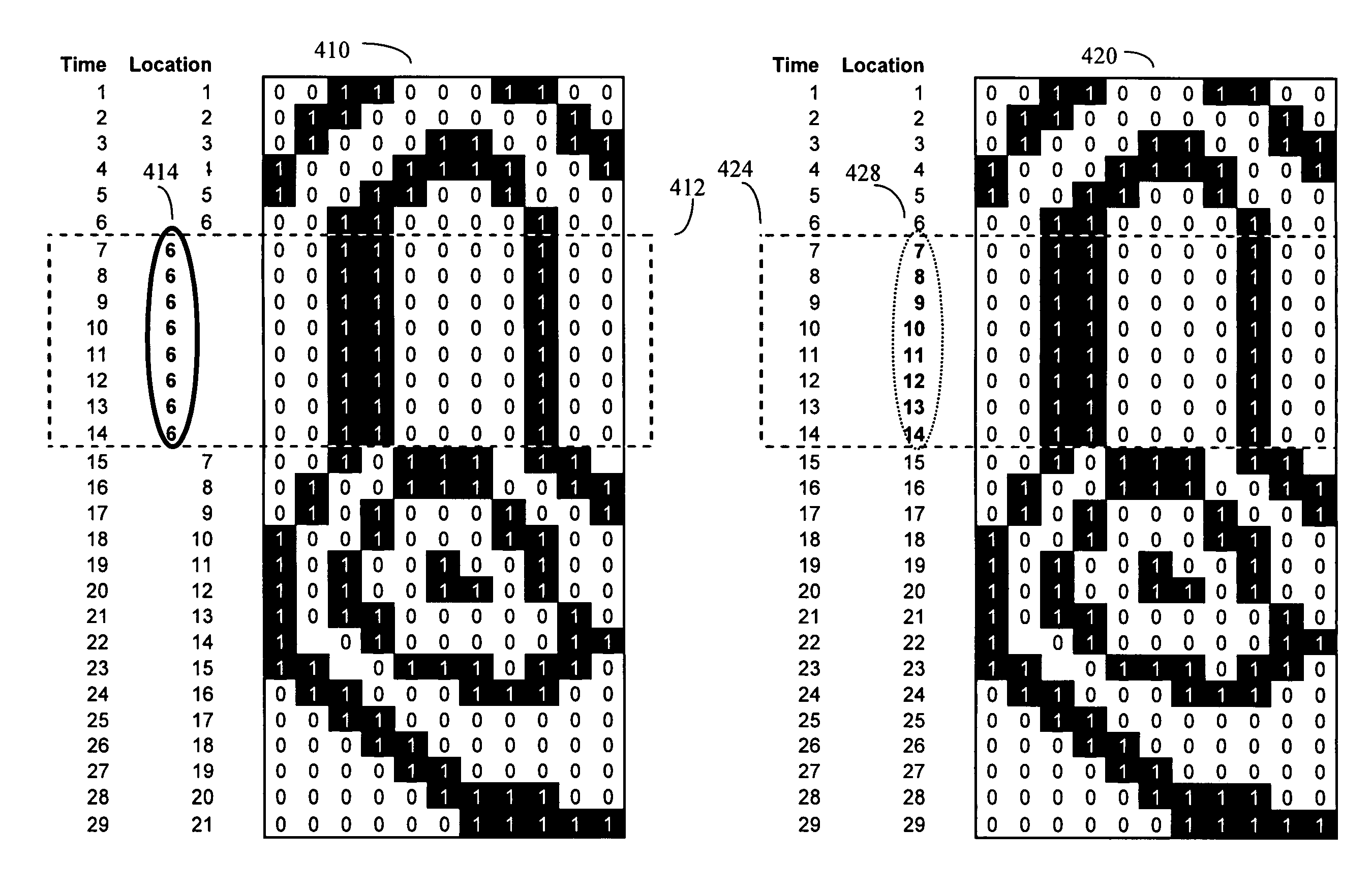
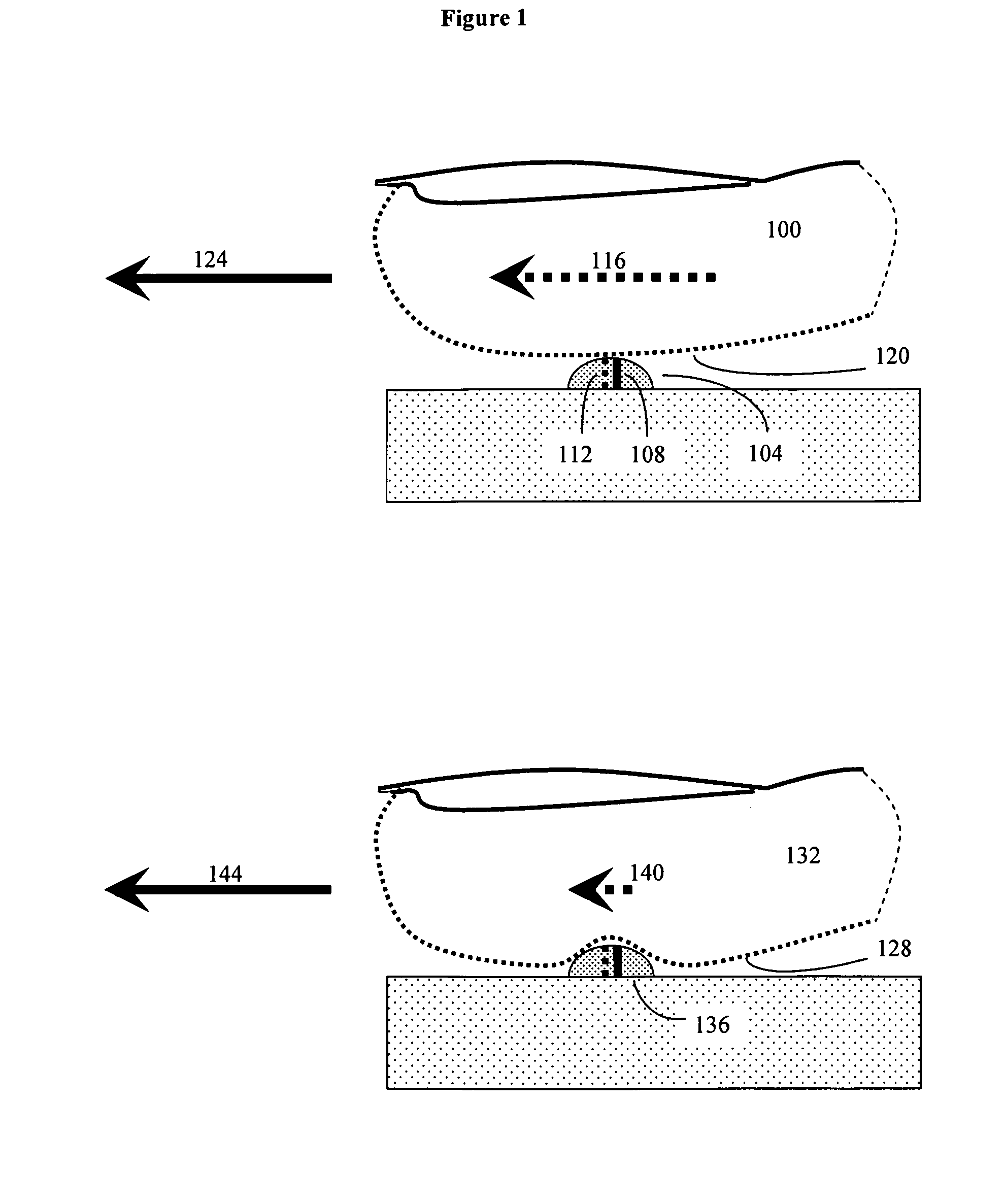
However, these different finger location stamps are misleading because during the stiction event, the finger pad skin itself may not have moved.
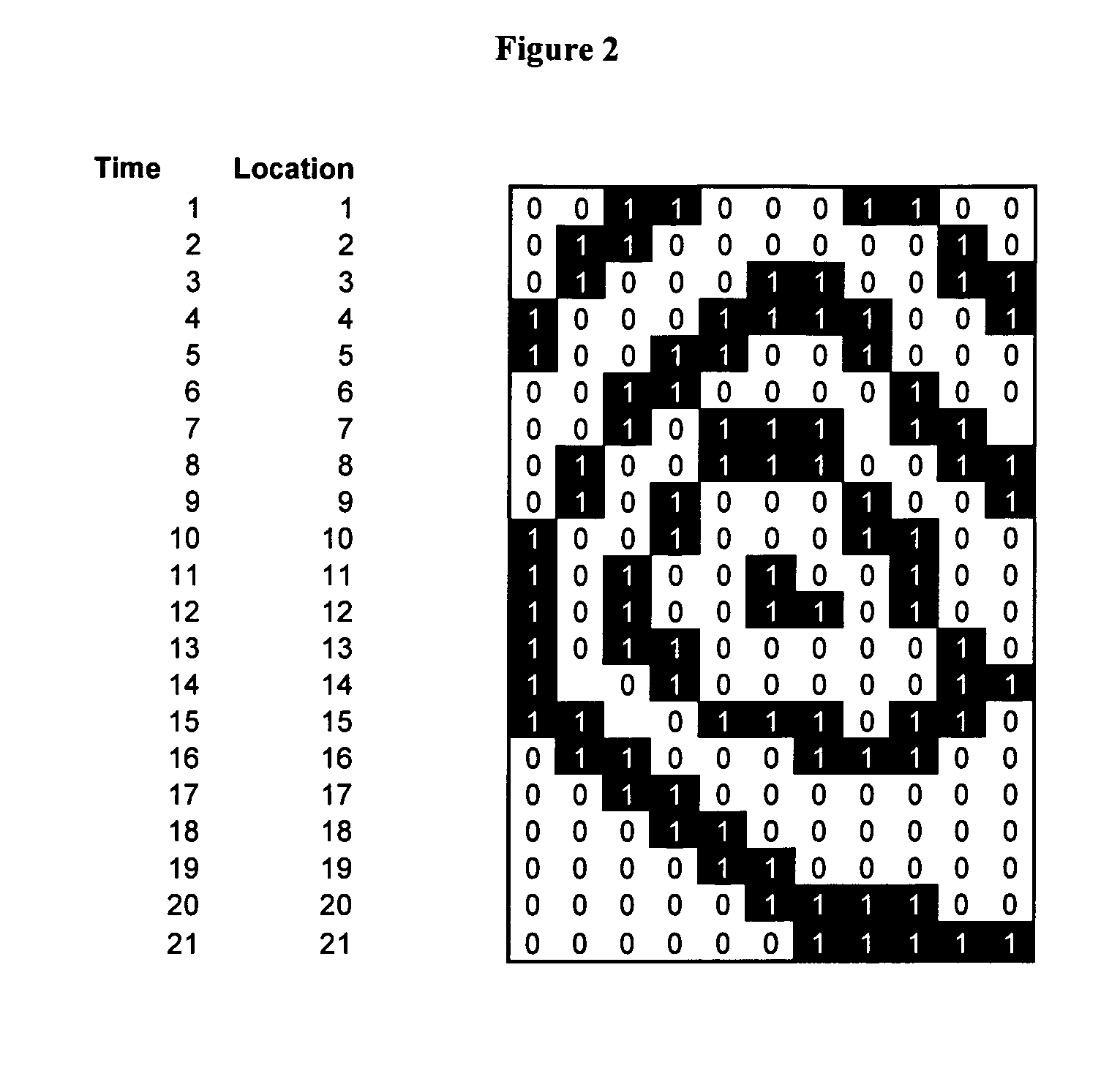
Thus when a processor connected to the partial fingerprint sensor attempts to reassemble the series of one dimensional images into a complete two dimensional fingerprint, a distorted image will result.
This distorted data is undesirable because it can confound security authorization schemes that require high quality, undistorted, fingerprint images.

Method used


Image

  • System and method to remove artifacts from fingerprint sensor scans
  • System and method to remove artifacts from fingerprint sensor scans
  • System and method to remove artifacts from fingerprint sensor scans

Examples


Embodiment Construction

[0027]In general, any biometric imaging system that operates on a partial image basis, and that may encounter distortions and artifacts due to improper motion of the biological target relative to the sensor, may be corrected by these methods. Examples of such biometric imaging systems include retinal scans, iris scans, hand prints, finger prints, and other types of scans. Although, throughout this disclosure, fingerprint stiction correction is used as an example of an image artifact that can be corrected by the present invention, it should be understood that the present methods are not limited to either stiction artifacts, or fingerprint scans.

[0028]The present invention is particularly useful for removing “stiction” artifacts from fingerprint scans recorded by one-dimensional partial fingerprint sensors. As previously discussed, such one dimensional partial fingerprint sensors generally consist of a linear array of individual sensor units, typically packed closely together at high ...


PUM


Abstract

A method and device for removing common artifacts, such as stiction, from fingerprint scans created by partial fingerprint scanners. The partial fingerprint scanner data is assessed to determine if successive partial fingerprint images are overly similar to each other, which can occur during stiction. If this similarity exceeds a preset threshold, then at least some of the overly similar partial images will be removed (redacted) from the overall image dataset. The complete overall image is generated from the redacted data set. This method is particularly useful for creating “intelligent” low-cost, low power partial fingerprint scanners and scanner driver chips that can pre-process the partial fingerprint data that is generated during the course of a finger swipe, and remove stiction artifacts on a real-time or near-real time basis using relatively simple and low power on-chip processing circuits, and then send the corrected data to more sophisticated processors for subsequent fingerprint analysis.

Description

BACKGROUND[0001]Partial fingerprint scanners are becoming popular for a wide variety of security applications. In contrast to “all at once” fingerprint scanners, which capture an image of an entire fingerprint at the same time, partial fingerprint sensing devices use a sensing area that is smaller than the fingerprint area to be imaged. By imaging only a portion of a fingerprint at any given time, the size and cost of a partial fingerprint sensor can be made considerably smaller and cheaper than that of a full fingerprint sensor. However to capture a full fingerprint image, the user must move his finger and “swipe” it across the sensing zone of the partial finger print sensor.[0002]Various types of partial fingerprint readers exist. Some work by optical means, some by pressure sensor means, and others by capacitance sensing means or radiofrequency sensing means.[0003]For example, one common configuration used for a fingerprint sensor is a one or two dimensional array of CCD (charge ...

Claims


Application Information

Patent Timeline
Patent Type & Authority Patents(United States)
IPC IPC(8): G06K9/00
CPCG06K9/00026G06K9/036G06V40/1335G06V10/993
Inventor SATYAN, PALLAVICHAN, PHILIP YIU KWONG
Owner SYNAPTICS INC
Why Eureka
Eureka Blog
Learn More