
Driving light emitting diodes

a technology of light-emitting diodes and driving lights, which is applied in the direction of electric variable regulation, process and machine control, instruments, etc., to achieve the effect of reducing the number of main power supplies

Active Publication Date: 2012-06-19
SIGNIFY HLDG BV
View PDF18 Cites 6 Cited by
  • Summary
  • Abstract
  • Description
  • Claims
  • Application Information

AI Technical Summary

Benefits of technology

The invention provides a system for driving a string of LED's that can adjust the spectral composition of the light emitted by the string while using a single main power supply. The system includes a driver that has a main power supply and a secondary power supply. The secondary power supply controls a smaller delta current to adjust the spectral composition of the light emitted by the string. The system can be used in a backlight unit for a display panel or in a display apparatus. The technical effect of the invention is to minimize the number of main power supplies required while still being able to adjust the spectral composition of the light emitted by the string.

Problems solved by technology

It is a disadvantage of the prior art apparatus that three SMPS's are required to be able to drive the differently colored LED strings such that their color point can be controlled.

Method used


Image

  • Driving light emitting diodes
  • Driving light emitting diodes
  • Driving light emitting diodes

Examples


Embodiment Construction

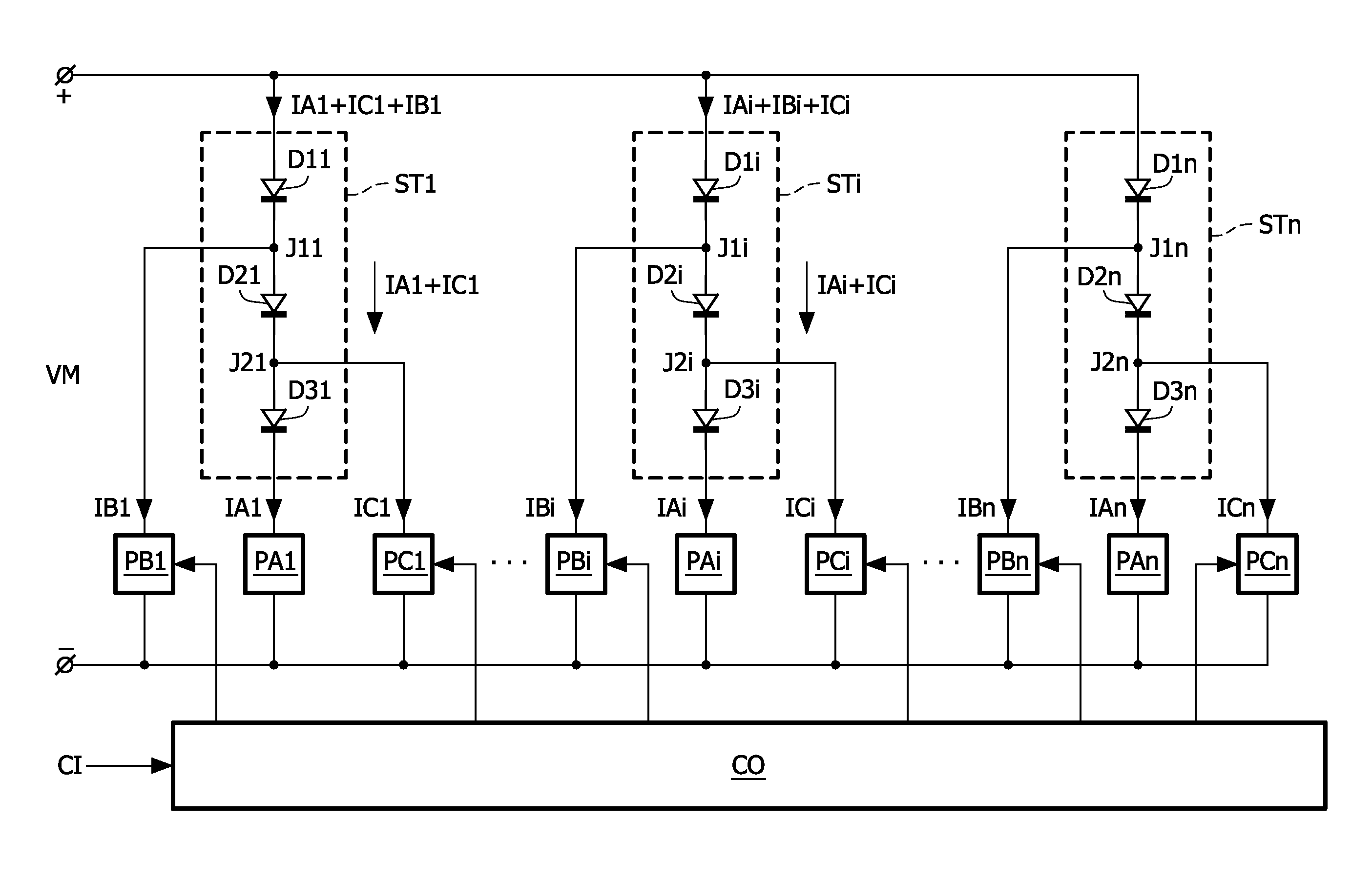
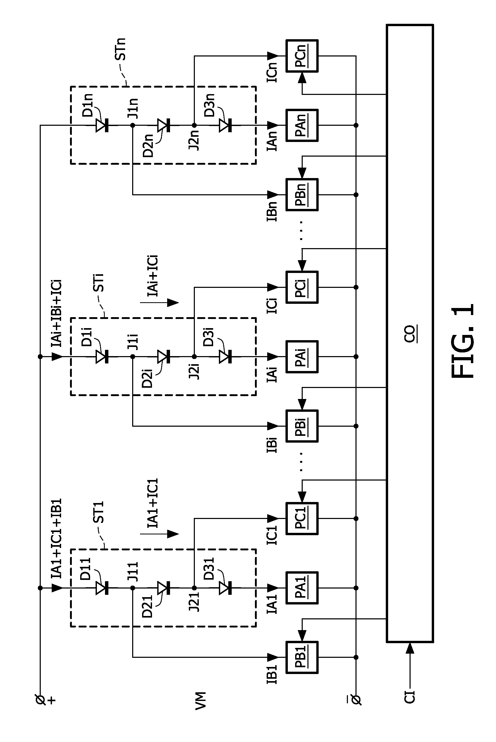
[0021]FIG. 1 schematically shows a block diagram of a backlight unit which comprises a plurality of strings of LED's and a plurality of power supplies driving the strings. Each of the n strings STi comprises, by way of example, three differently colored LED's D1i, D2i, D3i. The first string ST1 comprises a series arrangement of the three LED's D11, D12, D13, the ith string STi comprises a series arrangement of the three LED's D1i, D2i, D3i, and the nth string STn comprises a series arrangement of the three LED's D1n, D2n, D3n. In the now following the indices 1 to n are used to indicate a particular one of the n items. However, the index i is also used to indicate the item in general. Thus: “the LED's D1i” means the LED's D11 to D1n in general, or said differently, “the LED D1i” means an arbitrary one of the LED's D11 to D1n, and “the LED D11” means the particular LED D11.

[0022]Three power supplies PAi, PBi, PCi are associated with each of the strings STi. The main power supply PAi ...


PUM


Abstract

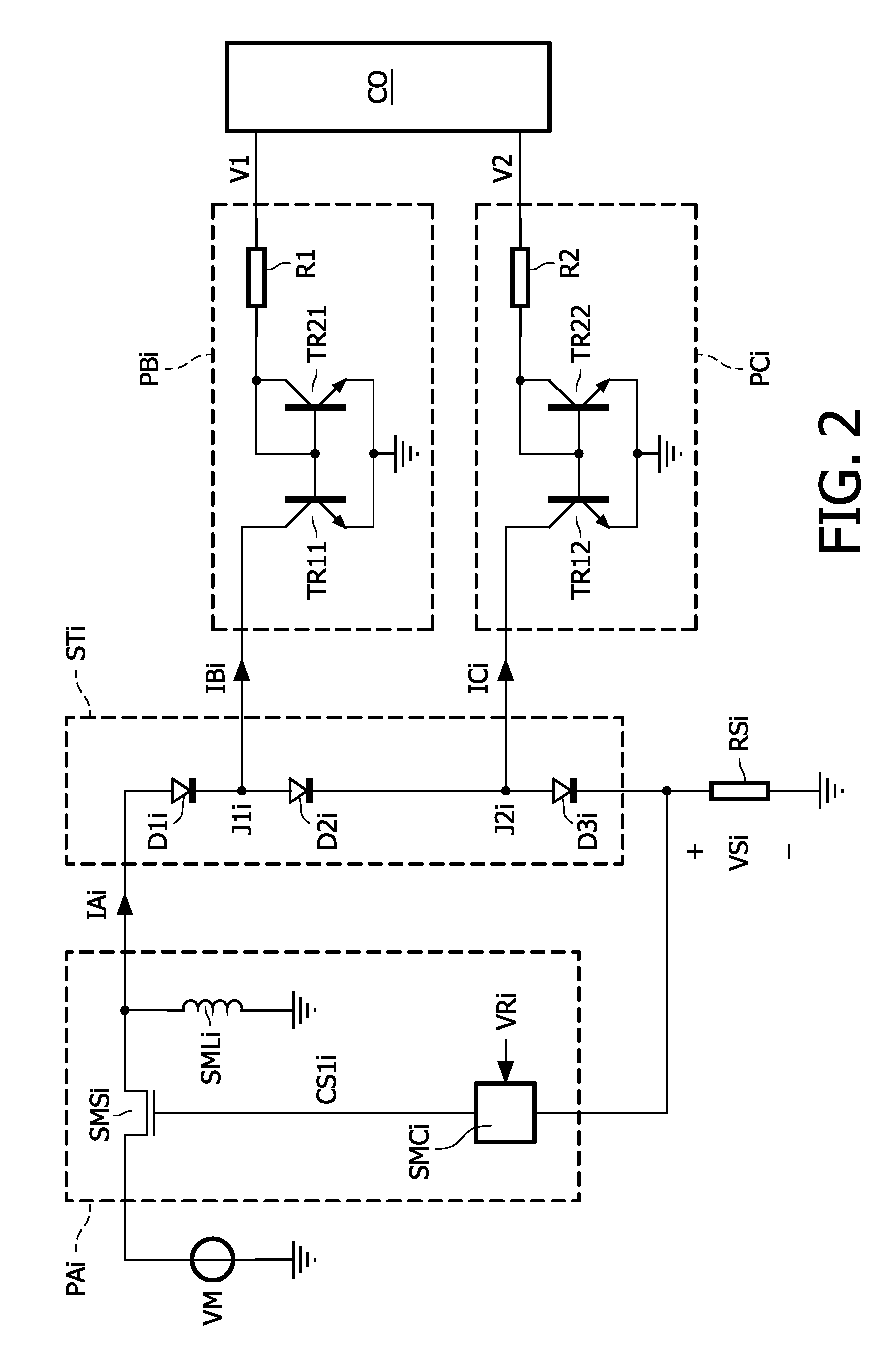
Disclosed is a driver that includes a main power supply that has outputs coupled across a string of light emitting diodes to supply a main current. A secondary power supply is coupled to a junction between successive light emitting diodes in the string to supply or withdraw a delta current from the junction. The delta current is at least five times smaller than the main current. A controller controls the secondary power supply to generate the delta current to obtain a desired spectral composition of the mixed light emitted by the string.

Description

FIELD OF THE INVENTION[0001]The invention relates to a driver for a string of series arranged light emitting diodes, to a system of a driver and the string of light emitting diodes, to a backlight unit for illuminating a display panel, to a system comprising the backlight unit and the display panel, and to a display apparatus comprising the backlight unit and the display panel.BACKGROUND OF THE INVENTION[0002]WO 02 / 076150 A1 discloses an apparatus which controls multiple light sources of which the light is mixed to obtain light of a predetermined color light. A processor compares the amount of light detected of each of the light sources with a desired amount and controls drivers of the light sources such that the light sources produce the desired light level. The light sources are three strings of red, blue and green light emitting diodes (further also referred to as LED's), respectively. Each string of LED's is driven by a separate switched mode power supply (further also referred ...

Claims


Application Information

Patent Timeline
Patent Type & Authority Patents(United States)
IPC IPC(8): H05B37/02H05B44/00
CPCH05B33/0815H05B33/0857H05B33/083H05B45/48H05B45/20H05B45/3725
Inventor PEETERS, HENRICUS MARIEVAN WOUDENBERG, ROELBREMER, PETRUS JOHANNES
Owner SIGNIFY HLDG BV
Learn More