Antenna radome

a technology of radome and antenna, applied in the direction of resonant antennas, substantially flat resonant elements, radiating element structural forms, etc., can solve the problems of enlarge the signal loss of the feeding network, the antenna array enlarges and the antenna gain cannot be effectively increased. achieve the effect of effective increasing the antenna gain and significantly reducing the volume of the antenna

Active Publication Date: 2012-06-05
IND TECH RES INST +1
View PDF21 Cites 7 Cited by
  • Summary
  • Abstract
  • Description
  • Claims
  • Application Information

AI Technical Summary

Benefits of technology

[0007]The invention is directed to an antenna radome capable of effectively increasing the antenna gain and significantly reducing the volume of the antenna.

Problems solved by technology

However, the practical application of the antenna array enlarges the signal loss of the feeding network.
As a result, the antenna gain can not be increased effectively.
Furthermore, the antenna array enlarges the volume of the antenna and therefore is not suitable for a small base station.

Method used


Image

  • Antenna radome
  • Antenna radome
  • Antenna radome

Examples


Embodiment Construction

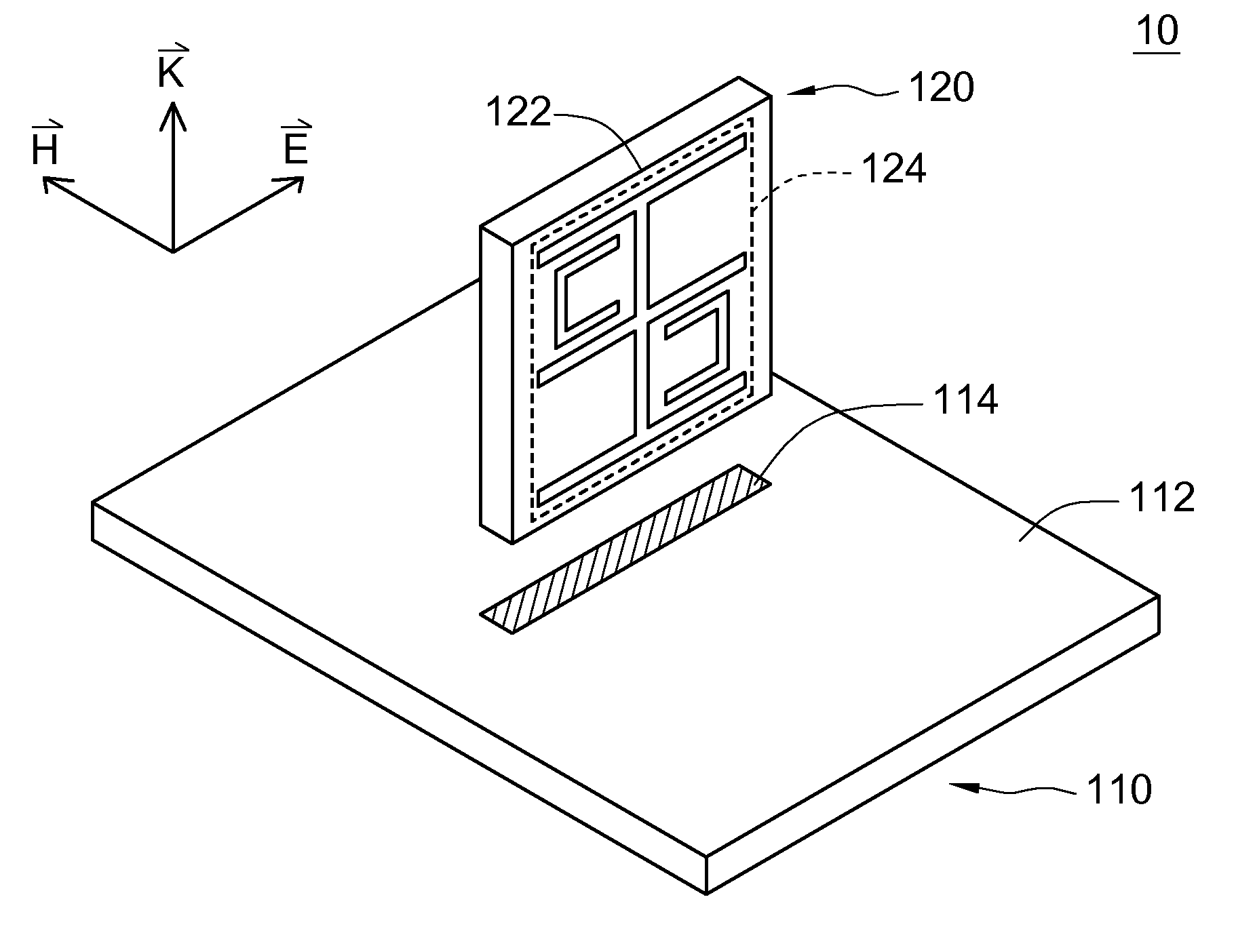
[0021]An antenna radome is provided in order to effectively increase the antenna gain and reduce the volume of an antenna. The antenna radome includes an antenna radome substrate and a unit cell. The unit cell is formed on a surface of the antenna radome substrate and perpendicular to a magnetic field direction of an antenna. The number of the antenna radome substrates and the unit cells can be adjusted flexibly according to the demands.

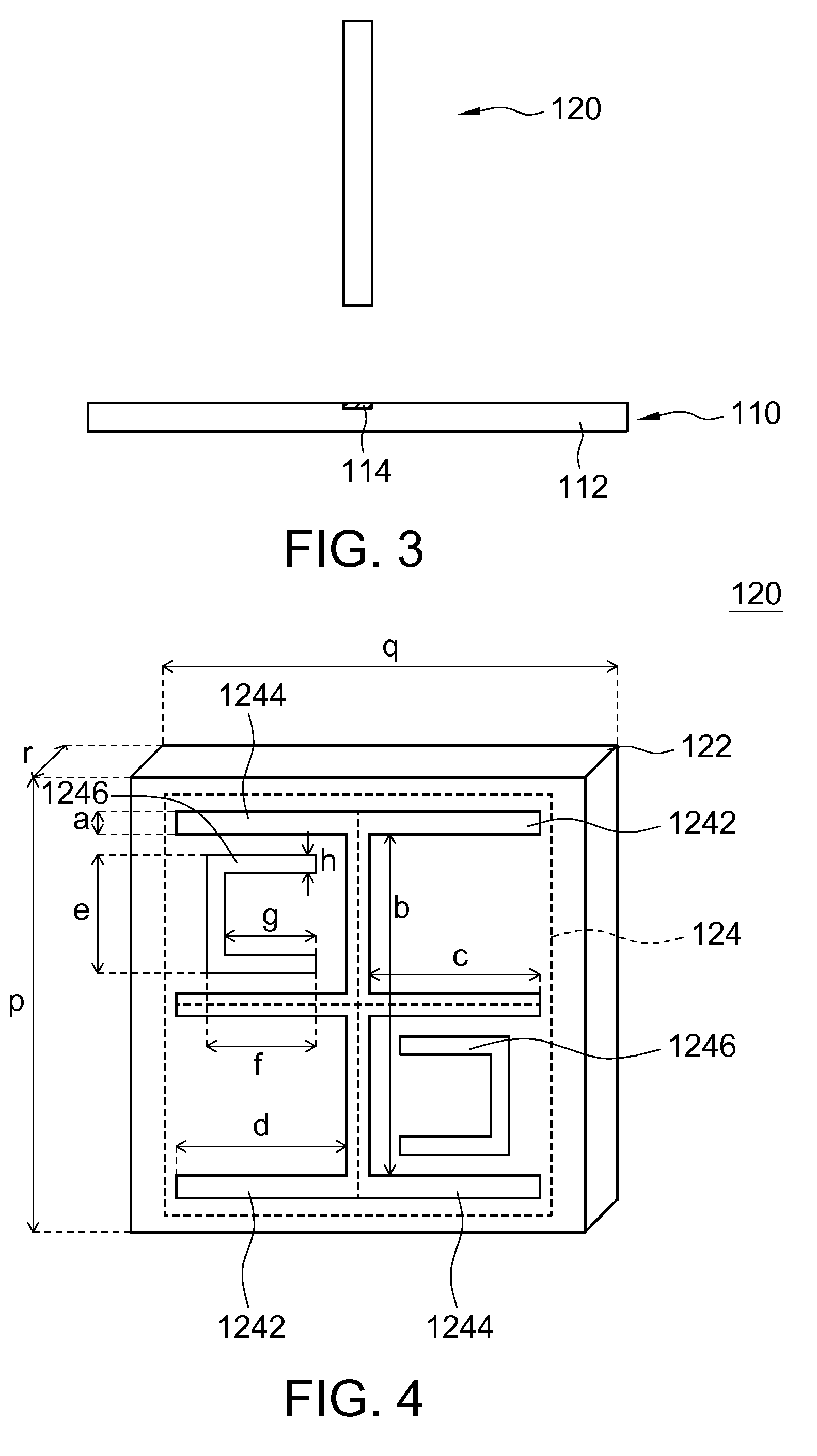
[0022]Please refer to FIG. 1, FIG. 2 and FIG. 3. FIG. 1 is a three-dimensional view of an antenna system according to a first embodiment of the present invention. FIG. 2 is a side view of the antenna system according to the first embodiment of the present invention. FIG. 3 is a front view of the antenna system according to the first embodiment of the present invention. The antenna system 10 includes an antenna 110 and an antenna radome 120. In the antenna system 10, a magnetic field direction {right arrow over (H)}, a radiation direction {right arrow...


PUM


Abstract

An antenna radome is provided. The antenna radome comprises an antenna radome substrate and a unit cell. The unit cell is formed on a surface of the antenna radome substrate, and the unit cell is perpendicular to a magnetic field direction of an antenna. The unit cell comprises a plurality of conductors.

Description

[0001]This application claims the benefit of Taiwan application Serial No. 97123319, filed Jun. 23, 2008, the subject matter of which is incorporated herein by reference.BACKGROUND OF THE INVENTION[0002]1. Field of the Invention[0003]The invention relates in general to an antenna radome, and more particularly to an antenna radome capable of increasing the antenna gain and reducing the volume of an antenna system.[0004]2. Description of the Related Art[0005]An antenna of a front-end circuit is a necessary component in a wireless communication system. The property of the antenna significantly affects the signal quality of the whole system. Generally speaking, the received signal strength depends on the receiving power of the receiving terminal, the transmitting power of the transmitting terminal, the antenna gain of the transmitting antenna and the antenna gain of the receiving antenna. Therefore, the increase of the antenna gain improves the signal quality of the wireless communicati...

Claims


Application Information

Patent Timeline
Patent Type & Authority Patents(United States)
IPC IPC(8): H01Q1/42
CPCH01Q19/06H01Q1/42H01Q1/422H01Q9/0407
Inventor WU, CHUN-YIHLIN, HUNG-HSUANLIN, KEN-HUANGLIN, KUN-HSIENYEH, YU-FENG
Owner IND TECH RES INST
Why Eureka
Try Eureka