
Backlight unit

a backlight unit and backlight technology, applied in the field of backlight units, can solve the problems of unwanted increase in manufacturing costs and yield declin

Inactive Publication Date: 2012-06-05
SEOUL SEMICONDUCTOR
View PDF9 Cites 27 Cited by
  • Summary
  • Abstract
  • Description
  • Claims
  • Application Information

AI Technical Summary

Benefits of technology

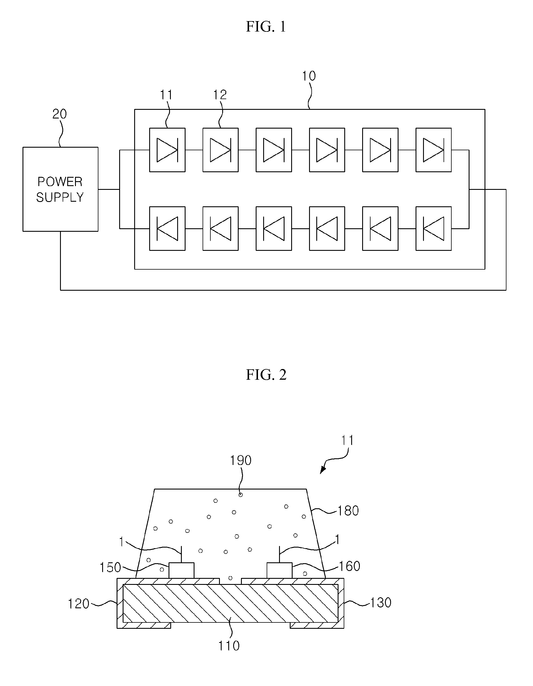
The present invention is about a backlight unit that uses LED packages to produce white light. The invention includes two LED packages, each containing different LED chips and phosphors that are excited by blue light to emit light that is mixed with the blue and green light emitted from the LED chips. The LED packages are arranged alternately, which helps to create a more uniform and complete mixing of the light. The technical effect of this invention is to provide a more efficient and effective way to produce white light using LED technology.

Problems solved by technology

However, when the backlight unit is implemented using an RGB full-color LED package or respective LED chips, there may be an unwanted increase in manufacturing costs and decrease in yield.

Method used


Image

  • Backlight unit
  • Backlight unit
  • Backlight unit

Examples


Embodiment Construction

[0020]The invention is described more fully hereinafter with reference to the accompanying drawings, in which exemplary embodiments of the invention are shown. This invention may, however, be embodied in many different forms and should not be construed as limited to the exemplary embodiments set forth herein. Rather, these exemplary embodiments are provided so that this disclosure is thorough, and will fully convey the scope of the invention to those skilled in the art. In the drawings, the size and relative sizes of layers and regions may be exaggerated for clarity. Like reference numerals in the drawings denote like elements.

[0021]It will be understood that when an element or layer is referred to as being “on” or “connected to” another element or layer, it can be directly on or directly connected to the other element or layer, or intervening elements or layers may be present. In contrast, when an element is referred to as being “directly on” or “directly connected to” another elem...


PUM


Abstract

The present invention relates to a backlight unit that includes at least one first light emitting diode (LED) package and at least one second LED package, wherein the first LED package includes a blue LED chip, a green LED chip, and a first phosphor, the first phosphor being excited by blue light and to emit light to be mixed with blue light and green light respectively emitted from the blue LED chip and the green LED chip, the first LED package to thereby emit white light; the second LED package includes a blue LED chip, a red LED chip, and a second phosphor, the second phosphor being excited by blue light and to emit light to be mixed with blue light and red light respectively emitted from the blue LED chip and the red LED chip, the second LED package to thereby emit white light; and the first LED package and the second LED package are alternately arranged.

Description

CROSS-REFERENCE TO RELATED APPLICATION[0001]This application claims priority from and the benefit of Korean Patent Application No. 10-2008-0030045, filed on Mar. 31, 2008, which is hereby incorporated by reference for all purposes as if fully set forth herein.BACKGROUND OF THE INVENTION[0002]1. Field of the Invention[0003]The present invention relates to a backlight unit for providing a white light source in a liquid crystal display.[0004]2. Discussion of the Background[0005]A liquid crystal display (LCD) typically includes an LCD panel having a thin film transistor (TFT) array substrate and a color filter substrate, which are opposite from and bonded to each other. The TFT array substrate and the color filter substrate are spaced apart from each other by a predetermined distance, and a liquid crystal layer is disposed in the space between the substrates. The LCD also includes a driver for driving the LCD panel, and a backlight unit for supplying backlight to the LCD panel.[0006]A c...

Claims


Application Information

Patent Timeline
Patent Type & Authority Patents(United States)
IPC IPC(8): H05B41/16
CPCG02F1/133603H01L25/0753H05B33/0821H05B33/0857G02F1/133609H01L33/50H01L2924/0002H01L2924/00H05B45/20H05B45/42G02F1/1335
Inventor CHO, WONJEONG, BI-YONG
Owner SEOUL SEMICONDUCTOR
Learn More