Pruning clipper for dispensing a chemical treatment

a technology for chemical treatment and clippers, which is applied in the direction of metal-working hand tools, insect catchers and killers, agriculture tools and machines, etc., can solve the problem of not operating to prevent future growth

Active Publication Date: 2012-05-22
BRIM III J CROSWELL
View PDF27 Cites 3 Cited by
  • Summary
  • Abstract
  • Description
  • Claims
  • Application Information

AI Technical Summary

Benefits of technology

[0003]A pruning clipper for dispensing a chemical treatment, such as a herbicide, on plants is disclosed herein. The clipper includes a pair of handles each having a distal end and a proximal end, with the handles being pivotally connected to each other close to the proximal ends of the handles. A first blade is connected to the proximal end of one of said handles, and a second blade is connected to the proximal end of the other handle. A chemical storage tank is connected to the distal end of one of said handles for storing a chemical to be selectively applied to vegetation. A bulb is connected to the proximal end of one of the handles, with the bulb being connected to the tank using a first connecting tube. A dispensing member extends along the side of one of the blades and beyond the blade to a dispersion point, and the dispensing member is connected to the bulb using a second connecting tube. As a result, the user will be able to cut the vegetation as desired using the clippers, and selectively dispense an herbicide as desired by the user.

Problems solved by technology

While these devices are useful to remove unwanted growth, they do not operate to prevent future growth on or near the plant or tree, and thus require the user to monitor the area and return to cut additional unwanted growth.

Method used


Image

  • Pruning clipper for dispensing a chemical treatment
  • Pruning clipper for dispensing a chemical treatment
  • Pruning clipper for dispensing a chemical treatment

Examples


Embodiment Construction

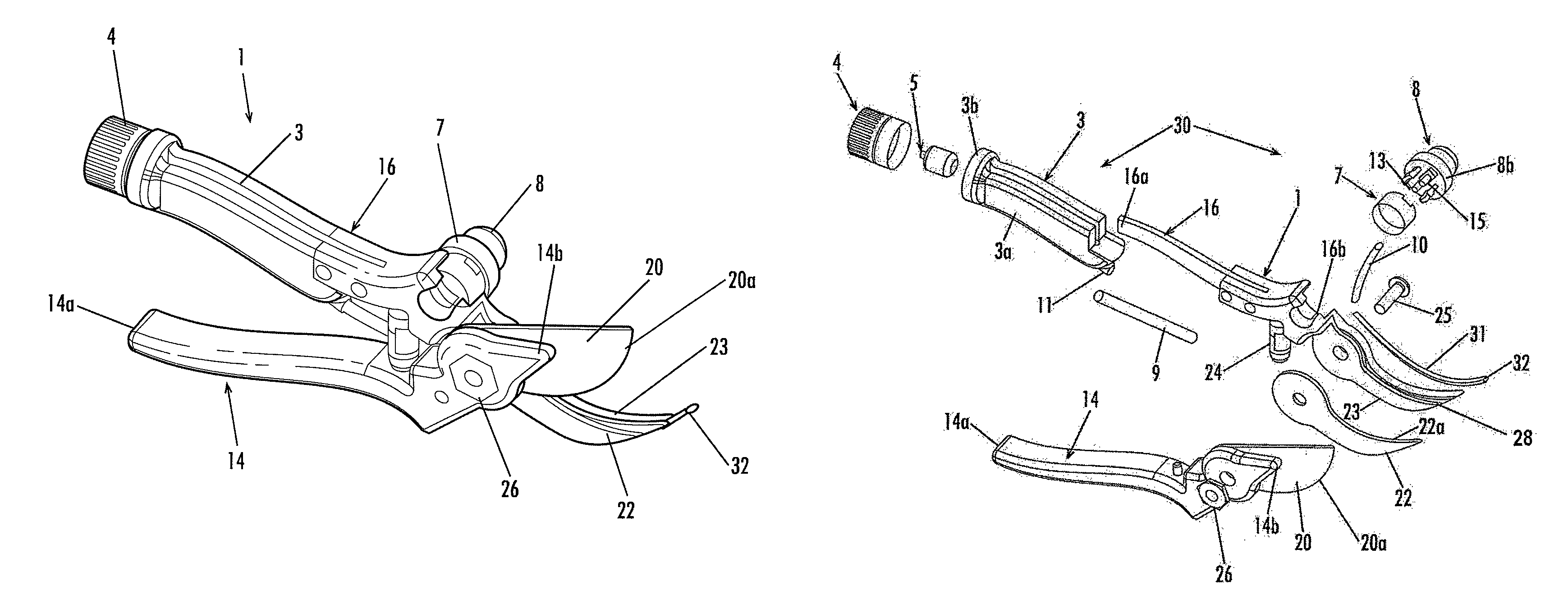
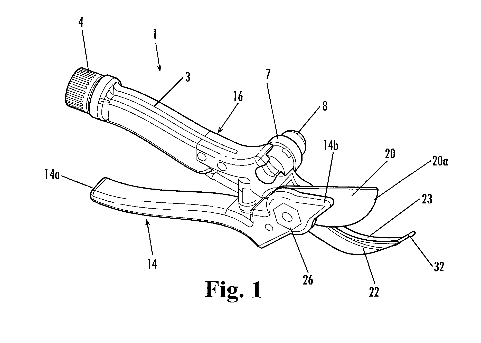
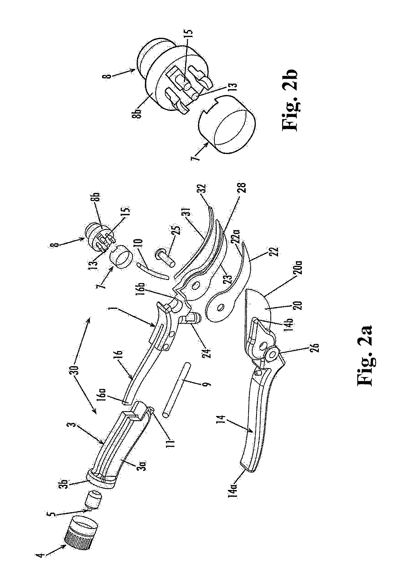
[0018]Looking to the attached Figures, an improved pruning clipper or pruning shear 1 providing a means for dispensing a chemical treatment is illustrated. Namely, FIGS. 1 through 3b show the pruning clipper 1 having first and second arm handles 14, 16 that are pivotally connected to each other via a connecting member 25, such as a bolt, screw, or similar means, connected to a nut 26 or similar mechanism. The first arm handle 14 has a distal end 14a and a proximal end 14b, with a first blade 20 connected to the proximal end 14b of the first arm handle 14. Likewise, the second arm handle 16 has a distal end 16a and a proximal end 16b, with a second blade 22 and blade mount 23 connected to the proximal end 16b of the second arm handle 16. The second blade 22 and blade mount 23 have similarly designed peripheral shapes, with the blade mount 23 further including a track or channel 28 along one surface of the blade mount 23, as described herein. The blades 20, 22 may be conventional hook...


PUM


Abstract

A pruning clipper includes a pair of handles each having a distal end and a proximal end, with the handles being pivotally connected to each other close to the proximal ends of the handles. A first blade is connected to the proximal end of one of said handles, and a second blade is connected to the proximal end of the other handle. A chemical storage tank is connected to the distal end of one of said handles for storing a chemical to be selectively applied to vegetation. A bulb is connected to the proximal end of one of the handles, with the bulb being connected to the tank using a first connecting tube. A dispensing member extends along the side of one of the blades and beyond the blade to a dispersion point, and the dispensing member is connected to the bulb using a second connecting tube. As a result, the user will be able to cut the vegetation as desired using the clippers, and selectively dispense an herbicide as desired by the user.

Description

CROSS REFERENCE TO RELATED PATENT APPLICATION[0001]This non-provisional application claims priority from provisional patent application 60 / 975,019, filed on Sep. 25, 2007, said application being relied upon and incorporated herein by reference.BACKGROUND OF THE INVENTION[0002]A variety of pruning shears are known and commonly used in cutting and trimming plants and trees, such as U.S. Pat. Nos. 4,073,059 and 5,743,018. While these devices are useful to remove unwanted growth, they do not operate to prevent future growth on or near the plant or tree, and thus require the user to monitor the area and return to cut additional unwanted growth.SUMMARY OF THE INVENTION[0003]A pruning clipper for dispensing a chemical treatment, such as a herbicide, on plants is disclosed herein. The clipper includes a pair of handles each having a distal end and a proximal end, with the handles being pivotally connected to each other close to the proximal ends of the handles. A first blade is connected to...

Claims


Application Information

Patent Timeline
Patent Type & Authority Patents(United States)
IPC IPC(8): A01G3/00
CPCA01G3/02
Inventor BRIM, III, J. CROSWELL
Owner BRIM III J CROSWELL
Why Eureka
Try Eureka