
Wind turbine

a wind turbine and wind power technology, applied in the direction of electric generator control, machines/engines, mechanical equipment, etc., can solve the problem that current wind turbines do not typically harness energy, and achieve the effect of simple and inexpensive components, enhanced wind turbine efficiency, and reduced nois

Inactive Publication Date: 2012-05-15
E NET
View PDF45 Cites 11 Cited by
  • Summary
  • Abstract
  • Description
  • Claims
  • Application Information

AI Technical Summary

Benefits of technology

"The present invention provides a wind turbine that can generate energy from low wind speeds and is portable and mountable on existing structures. The wind turbine includes a rotary shaft, turbine blades, magnets, and a coil. The blades are mounted on the shaft and can be designed to have a flexible membrane or asymmetrical cross-section to enhance efficiency. The wind turbine can also be attached to a spoked wheel with a central hub and spokes. The invention provides a wind turbine that can harness energy from wind at different speeds and reduce noise."

Problems solved by technology

This is due in part to the weight of the turbine blades and also in part to the friction in the gears between the turbine blade shaft and the generator.
Therefore, current wind turbines do not typically harness energy from wind speeds of less 8 mph.

Method used


Image

  • Wind turbine
  • Wind turbine
  • Wind turbine

Examples


first embodiment

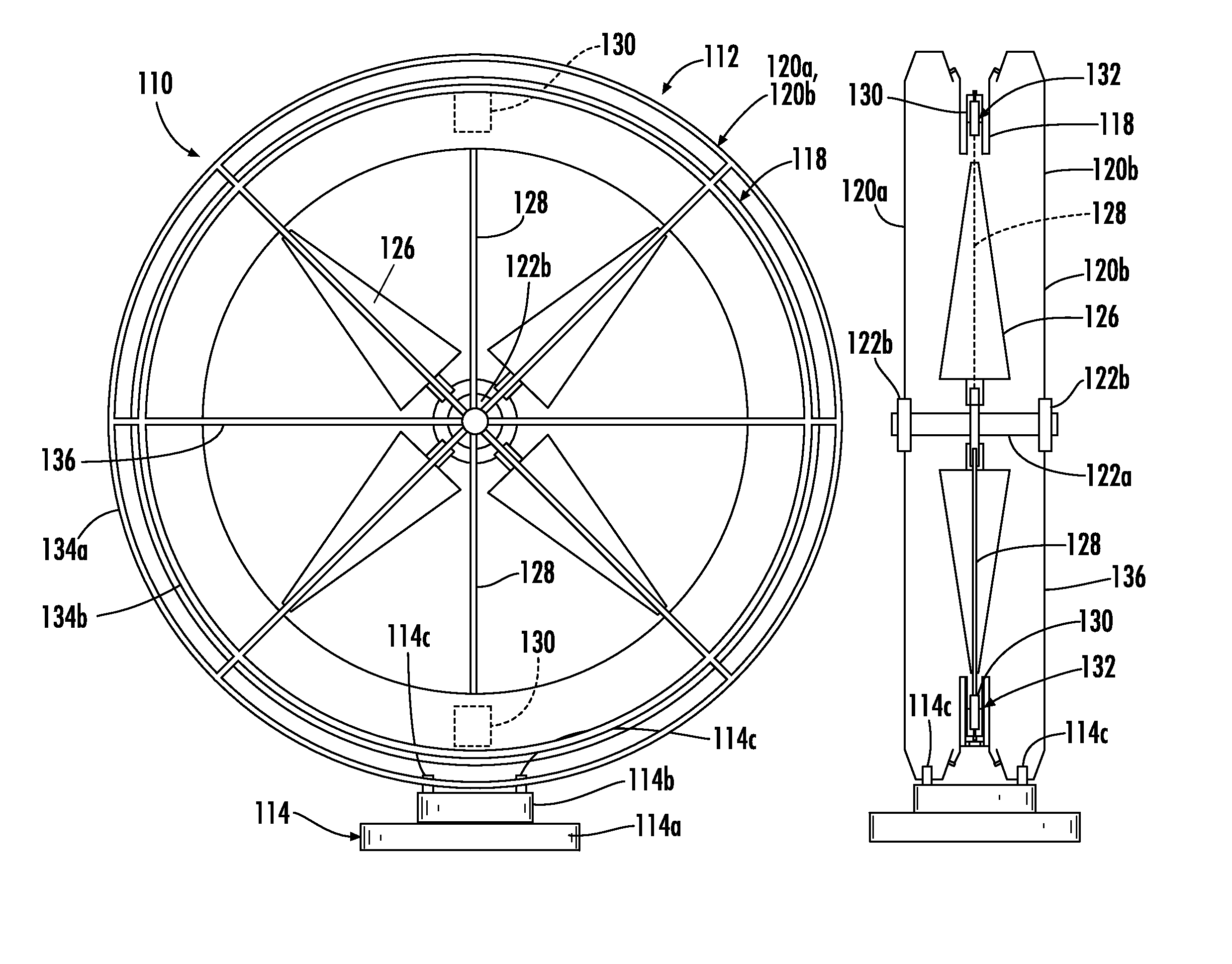
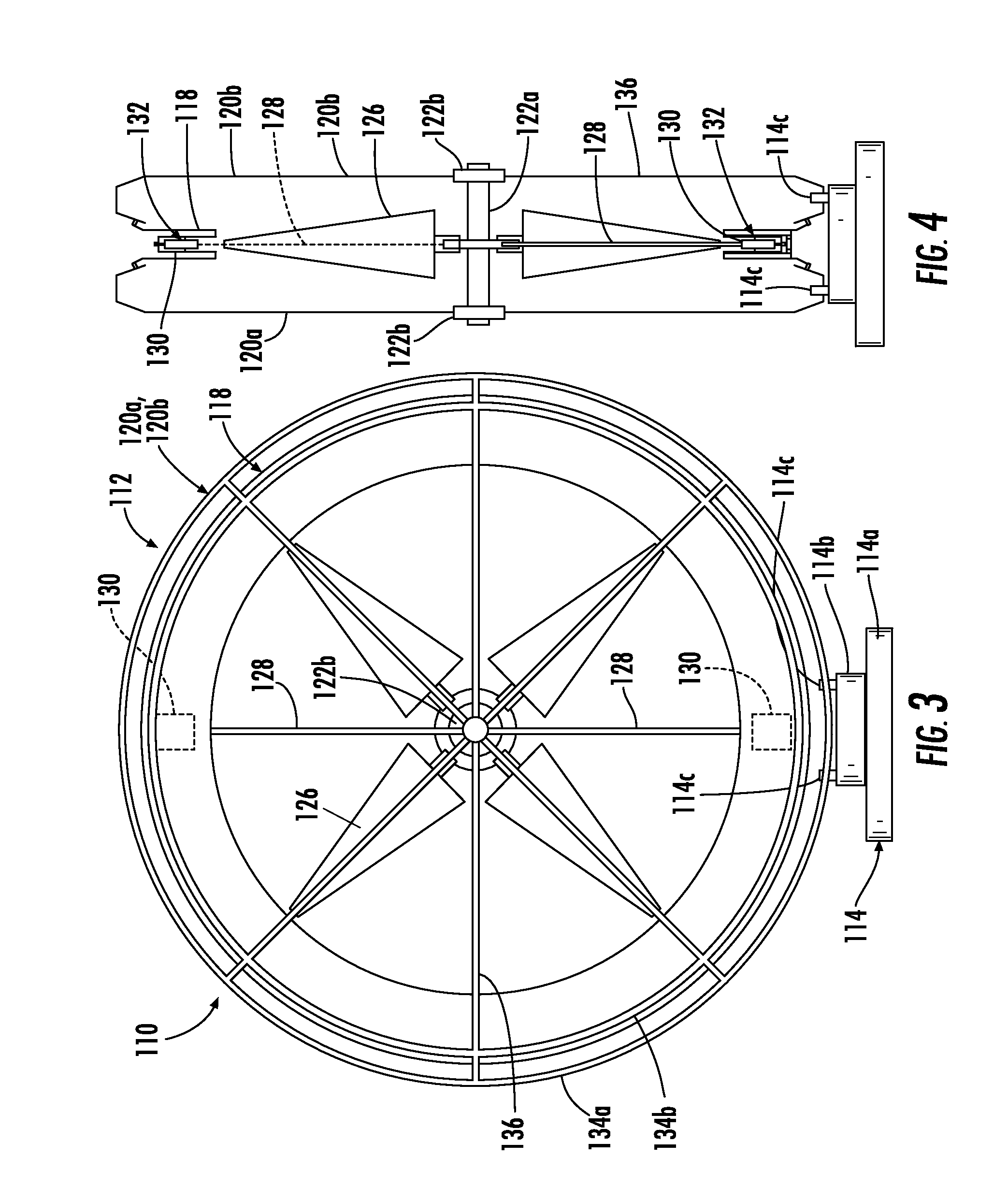
[0077]Annular member 118 is mounted between frame members 120a and 120b, inwardly of outer annular frame member 134a. Similarly to the previous embodiment, magnets 130 are mounted to arms 128, which are mounted to shaft 122a, such that magnets 130 extend into the stator coil assembly 132. In addition, with this configuration, magnets 130 have an angular velocity greater than the angular velocity of the hub that mounts turbine blade to shaft 122a and equal or greater than the angular velocity of the turbine blades. As noted in reference to the first embodiment, the arms rotate with the shaft 122a and are therefore rotated when the turbine blades rotate.

[0078]Referring to FIG. 5, annular member 118 is mounted to frame members 120a and 120b by fasteners and forms a stator coil assembly housing 140 for stator coil assembly 132. Housing 140 comprises a generally annular channel-shaped member that may extend around the full circumference of the turbine wheel, as shown so that it fully enc...

second embodiment

[0103]Referring to FIG. 20, the numeral 310 designates another embodiment of the wind turbine of the present invention. Similar to the previous embodiments, wind turbine 310 includes a frame 312, a turbine blade assembly 322 supported by frame 312 on a post 319, which supports the frame on a base 314. Similar to the second embodiment, base 314 comprises a fixed base portion 314a but supports post 319 for rotational motion about fixed base portion 314a. As best seen in FIG. 20, post 319 is mounted in base 314 by bearings 314b and, further, may be driven by a motor 314c housed in base 314, which is controlled by a control system such as disclosed in the above reference copending application, entitled WIND TURBINE AND CONTROL SYSTEM, which is incorporated by reference herein in its entirety. Further, in the illustrated embodiment, fixed base portion 314a may include a base plate 314e and a plurality of support legs 314d which are pivotally mounted to base plate 314e to allow the height...


PUM


Abstract

A wind turbine includes a rotary shaft having an axis of rotation, a plurality of turbine blades supported for rotary motion by the shaft, and a plurality of magnets supported by and spaced outwardly from the rotary shaft. The blades are mounted to the shaft by a mount that is radially inward of the magnets wherein the magnets have an annular velocity of at least the annular velocity of the blades. The turbine also includes a conductive coil, which is located outwardly from the magnets and the blades, wherein the coil surrounds the magnets and the blades and which is sufficiently close to the magnets such that rotary movement of the magnets induces current flow in the coil.

Description

[0001]This application claims the benefit of U.S. provisional application entitled WIND TURBINE, filed on May 20, 2009, Ser. No. 61 / 179,968, which is hereby incorporated by reference herein in its entirety, and is related to U.S. utility application entitled TURBINE ENERGY GENERATING SYSTEM, Ser. No. 12 / 138,818, filed Jun. 13, 2008, which is incorporated by reference herein in its entirety.TECHNICAL FIELD AND BACKGROUND OF THE INVENTION[0002]The present invention relates generally to a wind turbine and, more particularly, to a wind turbine that may operate at relatively low wind speeds while still generating electricity.[0003]Conventional wind turbines typically start to operate when the wind speed is at or above 8 mph. This is due in part to the weight of the turbine blades and also in part to the friction in the gears between the turbine blade shaft and the generator. Therefore, current wind turbines do not typically harness energy from wind speeds of less 8 mph. Given that wind s...

Claims


Application Information

Patent Timeline
Patent Type & Authority Patents(United States)
IPC IPC(8): F03D9/00F03D11/00
CPCF03D9/002H02K7/1869F05B2220/7066Y02E10/725F03D9/25F03D13/20F03D15/20Y02E10/72Y02E10/728
Inventor MAHAWILI, IMAD
Owner E NET
Learn More