Distortion compensation device for use in high-frequency power amplifier

a technology of distortion compensation and power amplifier, which is applied in the direction of amplifiers, amplifiers with semiconductor devices/discharge tubes, amplifiers, etc., can solve the problems of little non-linearity, interference with adjacent channels, and inability to obtain perfect linearity, etc., to achieve the effect of shortening the time required for obtaining the optimum distortion compensation characteristics

Inactive Publication Date: 2012-05-08
NEC CORP
View PDF16 Cites 18 Cited by
  • Summary
  • Abstract
  • Description
  • Claims
  • Application Information

AI Technical Summary

Benefits of technology

[0018]According to the present invention, even if the amplifier characteristics are varied, optimum distortion compensation characteristics can be automatically achieved, and it is possible to shorten the period of time required for obtaining the optimum distortion compensation characteristics.

Problems solved by technology

Such non-linear distortion brings about radiating unnecessary power outside a desired band for original signals and results in interference with an adjacent channel.
Actual power amplifiers however have not a little non-linearity, and it is impossible to obtain perfect linearity in them.

Method used


Image

  • Distortion compensation device for use in high-frequency power amplifier
  • Distortion compensation device for use in high-frequency power amplifier
  • Distortion compensation device for use in high-frequency power amplifier

Examples


Embodiment Construction

[0028]Embodiment of the present invention will be described with reference to the accompanying drawings.

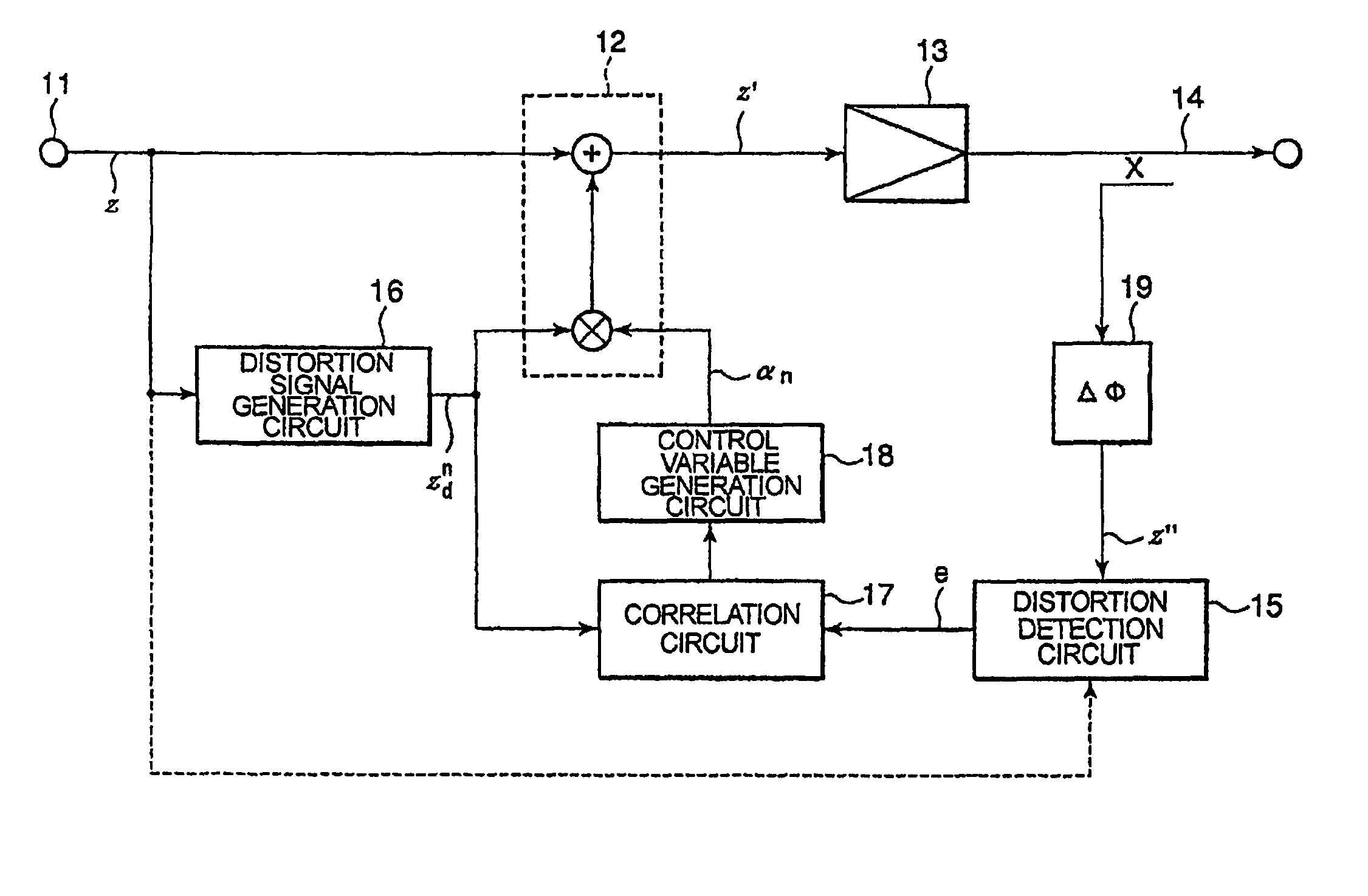
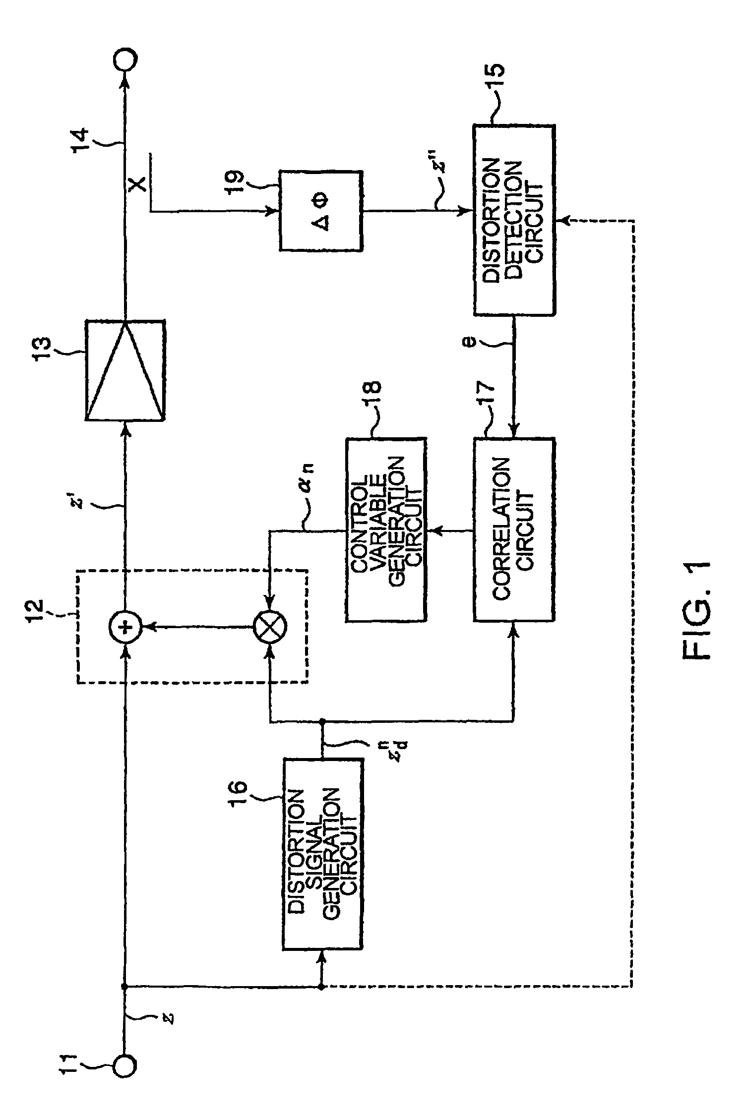
[0029]FIG. 1 is a circuit block diagram for explaining a distortion compensation device according to a first embodiment of the present invention. Overall operation of the device will be described using FIG. 1. A high-frequency signal to be amplified is input through an input terminal 11 to a distortion compensation signal generation circuit 12 and a distortion signal generation circuit 16. The distortion compensation signal generation circuit 12 supplies a power amplifier 13 with a signal to be amplified, as an amplifier input signal, and generates a distortion compensation signal for canceling the distortion component generated by a power amplifier 13 within the distortion compensation signal generation circuit 12 in a manner to be described later.

[0030]An output signal of the power amplifier 13 is supplied to an output terminal 14 and is partly given to a distortion detection ci...


PUM


Abstract

A non-linear distortion signal contained in output signal components from a high-frequency power amplifier is detected, while a non-linear distortion signal is generated from a high-frequency signal to be amplified. Correlation between this non-linear distortion signal and the detected non-linear distortion signal is determined, and a control variable is calculated based on the signal thus obtained. The obtained control variable is multiplied by the generated non-linear distortion signal to generate a distortion compensation signal, which is added to the signal to be amplified. This provides a distortion compensation device capable of automatically maintaining optimum distortion compensation characteristics and rapidly achieving desirable distortion compensation.

Description

TECHNICAL FIELD[0001]The present invention relates to a device for compensating non-linear distortion occurring during power amplification of high-frequency signals.BACKGROUND ART[0002]On amplifying high-frequency signals, linearity is required between input and output signals when an envelope of the input signal is varied with time. This is because absence of linearity will cause occurrence of so-called non-linear distortion (hereafter, referred to as “distortion”). Such non-linear distortion brings about radiating unnecessary power outside a desired band for original signals and results in interference with an adjacent channel.[0003]Actual power amplifiers however have not a little non-linearity, and it is impossible to obtain perfect linearity in them. In general, power efficiency of the power amplifier, namely, a rate of power of high-frequency signals to the power of the power source tends to be reduced when placing importance on the linearity. In contrast, the non-linearity wi...

Claims


Application Information

Patent Timeline
Patent Type & Authority Patents(United States)
IPC IPC(8): H04B1/04
CPCH03F1/3247
Inventor AKAIWA, YOSHIHIKO
Owner NEC CORP
Why Eureka
Try Eureka