Method for transmission using a non-uniform interconnection
a transmission method and non-uniform technology, applied in the direction of line-transmission details, waveguide type devices, cross-talk reduction, etc., can solve the problems of not being able to build an interconnection, and the method is subject to three detrimental phenomena
- Summary
- Abstract
- Description
- Claims
- Application Information
AI Technical Summary
Benefits of technology
Problems solved by technology
Method used
Image

Examples
first embodiment
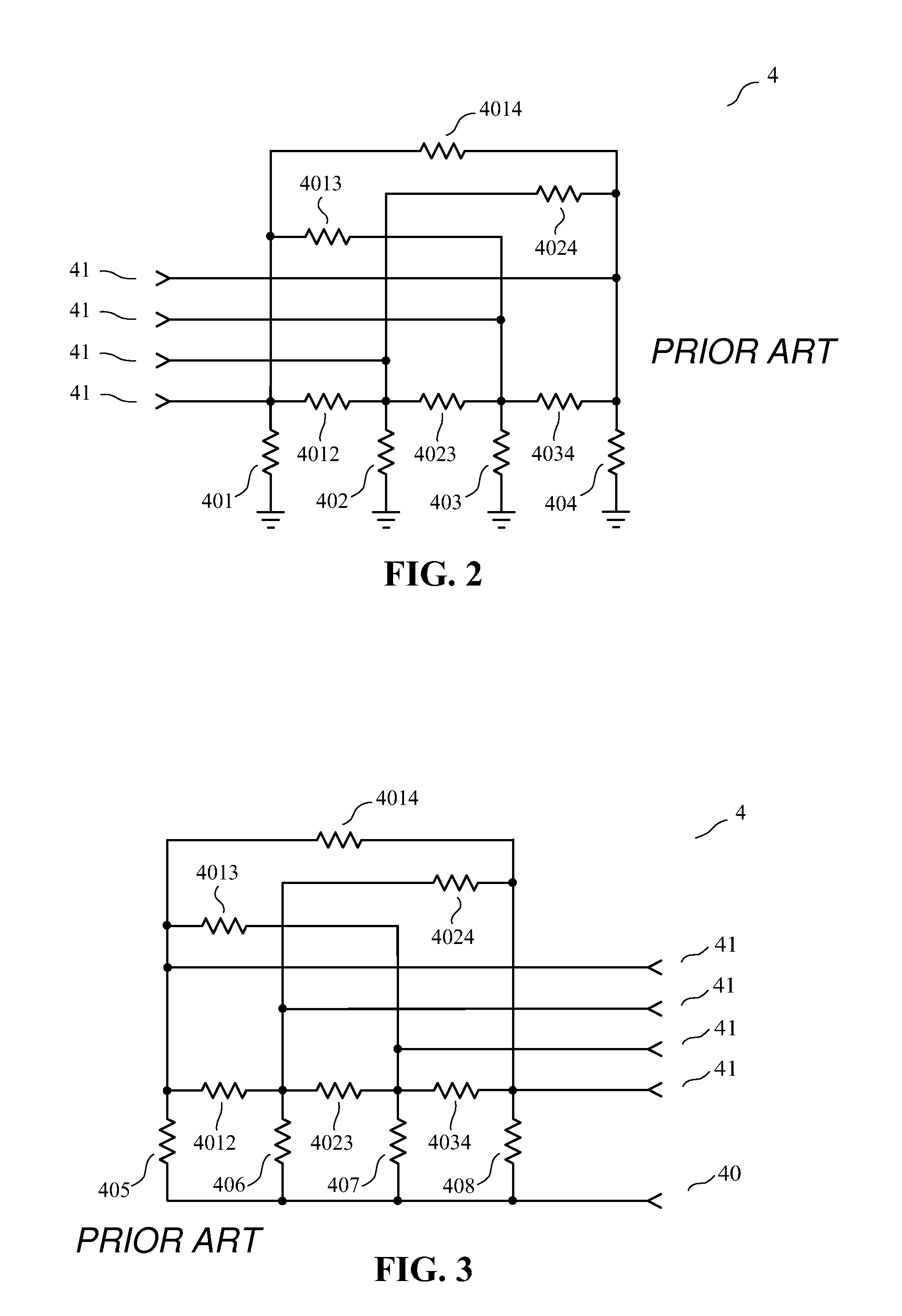
[0107]In the case where a termination circuit of a device for implementing the method of the invention is built inside an integrated circuit, it is possible to use a termination circuit comprising a common terminal, in a manner similar to the use described in said French patent application Ser. No. 08 / 03876 and the corresponding international application. For n=4, a non-limiting example of such a termination circuit is shown in FIG. 3 (FIG. 3 being presented above, in the prior art section). In this case, the common terminal node of the termination circuit is not grounded inside said integrated circuit, but the common terminal of the termination circuit is nevertheless coupled to the reference conductor of the interconnection, as explained above.
[0108]In the first circumstance, for the design of a transmitting circuit or of a receiving circuit, it is possible to use the design equations presented in the Section V of said article entitled “A New Method for the Reduction of Crosstalk ...
second embodiment
[0120]FIG. 7 shows a cross section of the interconnection used in a second embodiment;
[0121]FIG. 8 shows a cross section of the interconnection used in the first embodiment, with indication of several dimensional parameters;
[0122]FIG. 9 shows a cross section of the interconnection used in the second embodiment, with indication of several dimensional parameters;
[0123]FIG. 10 shows the second embodiment of the invention;
third embodiment
[0124]FIG. 11 shows the invention.
DETAILED DESCRIPTION OF SOME EMBODIMENTS
[0125]First Embodiment
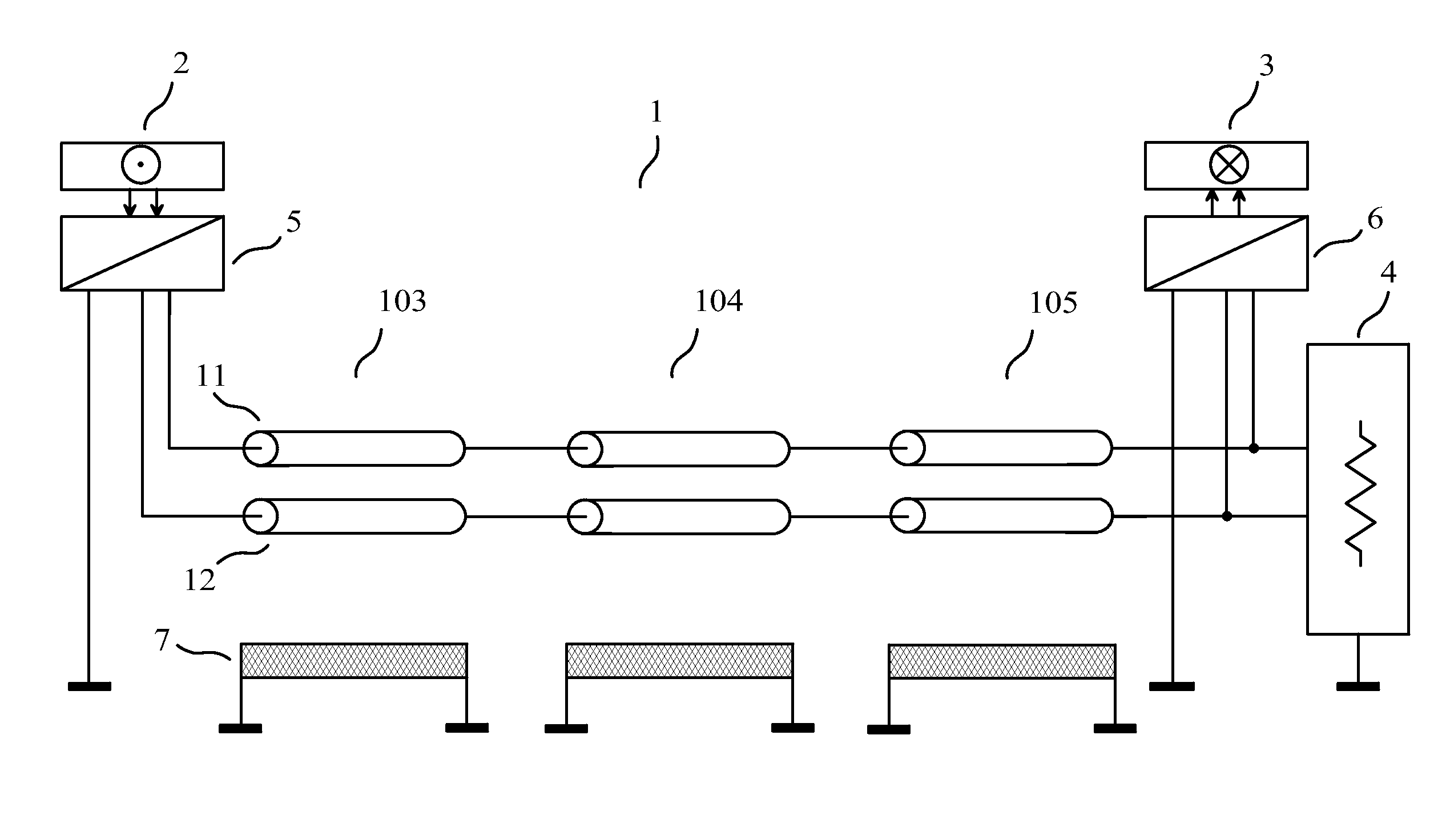
[0126]As a first embodiment of a device for implementing the method of the invention, given by way of non-limiting example, we have represented in FIG. 5 a device of the invention comprising an interconnection (1) having n=2 transmission conductors (11) (12) and a reference conductor (7). A transmitting circuit (5) receives at its input the m=2 “input signals of the transmitting circuit” from the m channels of the source (2). The transmitting circuit (5) comprises n output terminals which are connected to the transmission conductors (11) (12) of the interconnection (1), at the near-end of the interconnection (1). A termination circuit (4) is connected to ground and to the transmission conductors (11) (12) of the interconnection (1), at the far-end of the interconnection (1). A receiving circuit (6) is connected to the transmission conductors (11) (12) of the interconnection (1), at the fa...
PUM
 Abstract
Description
Claims
Application Information
 - R&D
- Intellectual Property
- Life Sciences
- Materials
- Tech Scout
- Unparalleled Data Quality
- Higher Quality Content
- 60% Fewer Hallucinations
Browse by: Latest US Patents, China's latest patents, Technical Efficacy Thesaurus, Application Domain, Technology Topic, Popular Technical Reports.
© 2025 PatSnap. All rights reserved.Legal|Privacy policy|Modern Slavery Act Transparency Statement|Sitemap|About US| Contact US: help@patsnap.com