Eureka AIR delivers breakthrough ideas for toughest innovation challenges, trusted by R&D personnel around the world.

Top for a convertible

a convertible and top technology, applied in vehicle sealing arrangements, engine seals, roofs, etc., can solve the problems of large construction space being occupied by the top, surface bow jamming or rattling, and the top occupies a relatively large amount of construction space. , to achieve the effect of simple kinematic structure of a tensioning bow

Active Publication Date: 2012-05-01
WEBASTO EDSCHA CABRIO
View PDF13 Cites 5 Cited by
  • Summary
  • Abstract
  • Description
  • Claims
  • Application Information

AI Technical Summary

Benefits of technology

[0011]It is a first object of the invention to provide a top for a convertible, which top has a space-saving and simple kinematic structure for a tensioning bow.
[0014]By means of the articulated connection of the second surface bow to the main link mechanism, the second surface bow can be displaced with respect to the main link mechanism in a play-free manner during opening and closing of the top. This eliminates the risk of rattling, jamming or the like. During opening and closing of the top, the articulated connection of the second surface bow to the main link mechanism ensures that the second surface bow is displaced in a space-saving manner with respect to the first surface bow located in front of it, and its displacement fits harmoniously into the overall sequence of movement of the kinematic structure of the main link mechanism.
[0015]Expediently, the main link mechanism can be designed as a main four-bar linkage, with the main pillar as front link and the main link as rear link. In this case, the body-mounted main bearing unit defines a base of the main four-bar linkage, wherein the main pillar and the main link are connected to each other in an articulated manner by means of a main coupling member. The second surface bow can be connected in an articulated manner to the main pillar by means of one of the first supporting link and the second supporting link in a portion of the second surface bow in the vicinity of the front edge or adjacent thereto and the second surface bow can be connected in an articulated manner to the main link by means of the other of the first supporting link and the second supporting link in a portion of the second surface bow in the vicinity of the rear edge or adjacent thereto. This expediently results, during opening of the top from a closed state of the top, in the second surface bow being able to be displaced below the first surface bow and forward in a direction towards the first surface bow when the main link mechanism is pivoted rearward with respect to the main bearing unit. If the top according to the invention is designed as a soft top with a top cloth which, in the closed position of the top, bears on the outside under tension at least against the first and second surface bows, the abovementioned kinematic structure for the second surface bow affords the advantage that, during opening and closing of the top, pivoting of the first surface bow and the second surface bows does not result in overstretching of the fabric in a region between a rear edge of the front bow and a front edge of the rear window. This effect is also assisted in that, during rearward pivoting of the main four-bar linkage, the second surface bow is shifted, inclined obliquely, below the first surface bow.
[0021]The four-bar linkage comprises a front link and a rear link, wherein the rear link is defined by a lower part of the second connecting link of the chain of links by which the front edge of the rear window frame is coupled to the main bearing unit. The coupling of the tensioning bow to the main bearing unit by means of a four-bar linkage permits a space-saving and precise displacing of the tensioning bow during opening and closing of the top, wherein the tensioning bow is operated via the second connecting link which is connected in an articulated manner via the intermediate link to the main link of the main four-bar linkage. Accordingly, during pivoting of the main four-bar linkage relative to the main bearing unit, the tensioning bow is displaced automatically in a translatory manner.
[0027]The coupling of the tensioning bow to the main bearing unit by means of the abovementioned four-bar linkage permits a space-saving and precise displacing of the tensioning bow during opening and closing of the top, wherein the tensioning bow is operated via the lowering link which is connected in an articulated manner via the intermediate link to a main link or a main pillar of the main link mechanism in the form of a main four-bar linkage. Accordingly, during pivoting of the main four-bar linkage relative to the main bearing unit, the tensioning bow is displaced automatically in a translatory manner.
[0028]Expediently, the top can comprise a first surface bow and a second surface bow which is connected in an articulated manner to the main link mechanism, wherein, when the top is closed, the first surface bow is arranged between the front bow and the second surface bow. The main link mechanism is expediently designed as a main four-bar linkage, with a front main pillar and a rear main link. In this case, the body-mounted main bearing unit forms the base of the main four-bar linkage, wherein the main pillar and the main link are connected to each other in an articulated manner by means of a main coupling member. The second surface bow can be connected in an articulated manner at its front edge to the main pillar by means of a first supporting link and can be connected in an articulated manner at its rear edge to the main link by means of a second supporting link. This expediently results, during opening of the top from a closed state of the top, in the second surface bow being able to be displaced below the first surface bow and forward in a direction towards the first surface bow when the main link mechanism is pivoted rearward with respect to the main bearing unit. If the top according to the invention is designed as a soft top with a top cloth which, in the closed position of the top, bears under tension at least against the first and second surface bows, the abovementioned kinematic structure for the second surface bow affords the advantage that during opening and closing of the top, pivoting of the first and second surface bows does not result in overstretching of the fabric between a rear edge of the front bow and a front edge of the rear window. This effect is also assisted in that, during rearward pivoting of the main four-bar linkage, the second surface bow is displaced, inclined obliquely, below the first surface bow.

Problems solved by technology

In the stowed position, because of the comparatively large longitudinal extent of its roof elements, said top takes up a relatively large amount of construction space.
In the case of this top too, the individual partial roof sections have a comparatively large longitudinal extent which, in the stowed position of the top, disadvantageously results in a large construction space being occupied by the top.
Such a solution has the disadvantage that the sliding guide may result in jamming or rattling of the surface bow or the like.

Method used


Image

  • Top for a convertible
  • Top for a convertible
  • Top for a convertible

Examples


Embodiment Construction

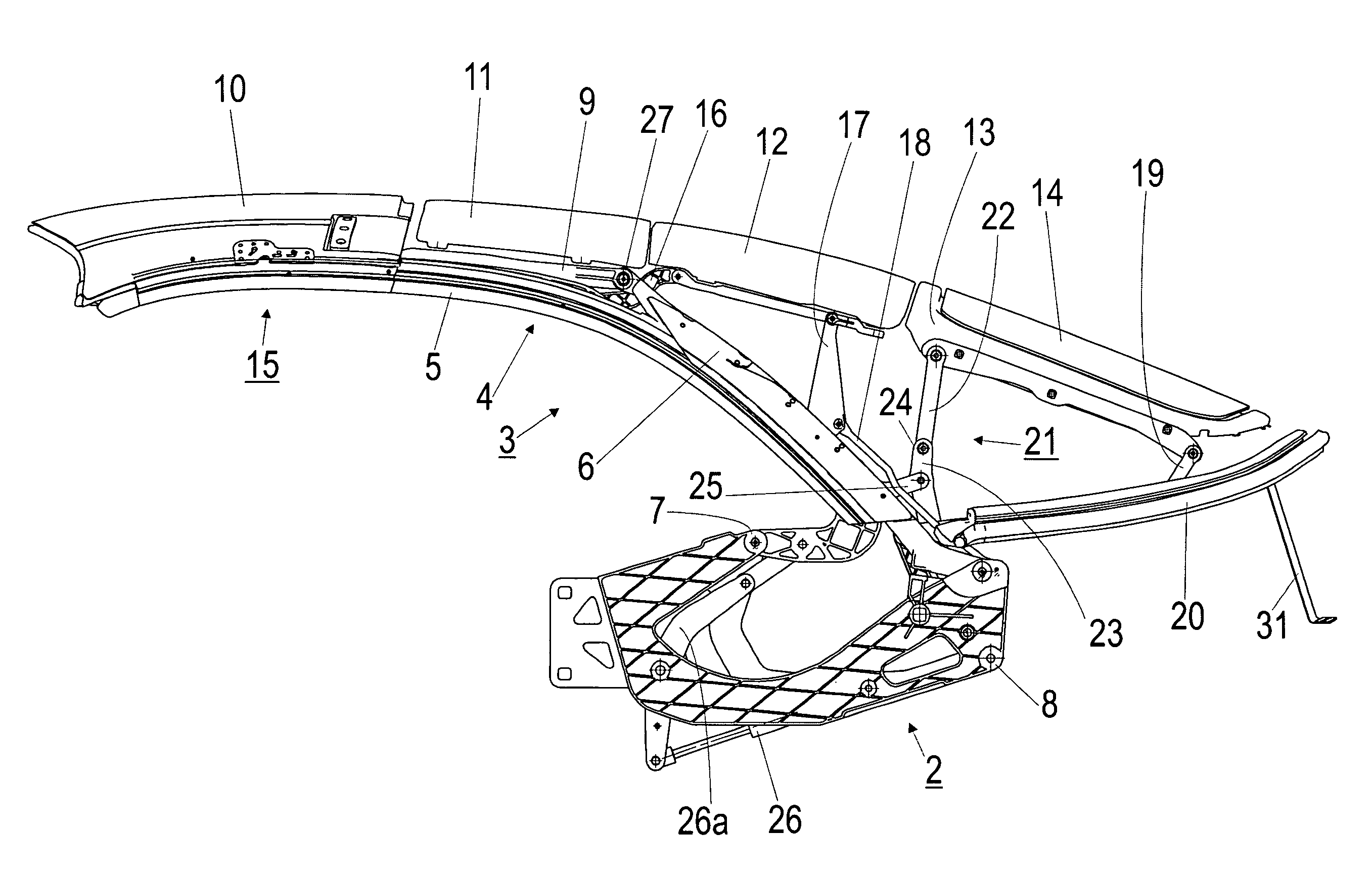
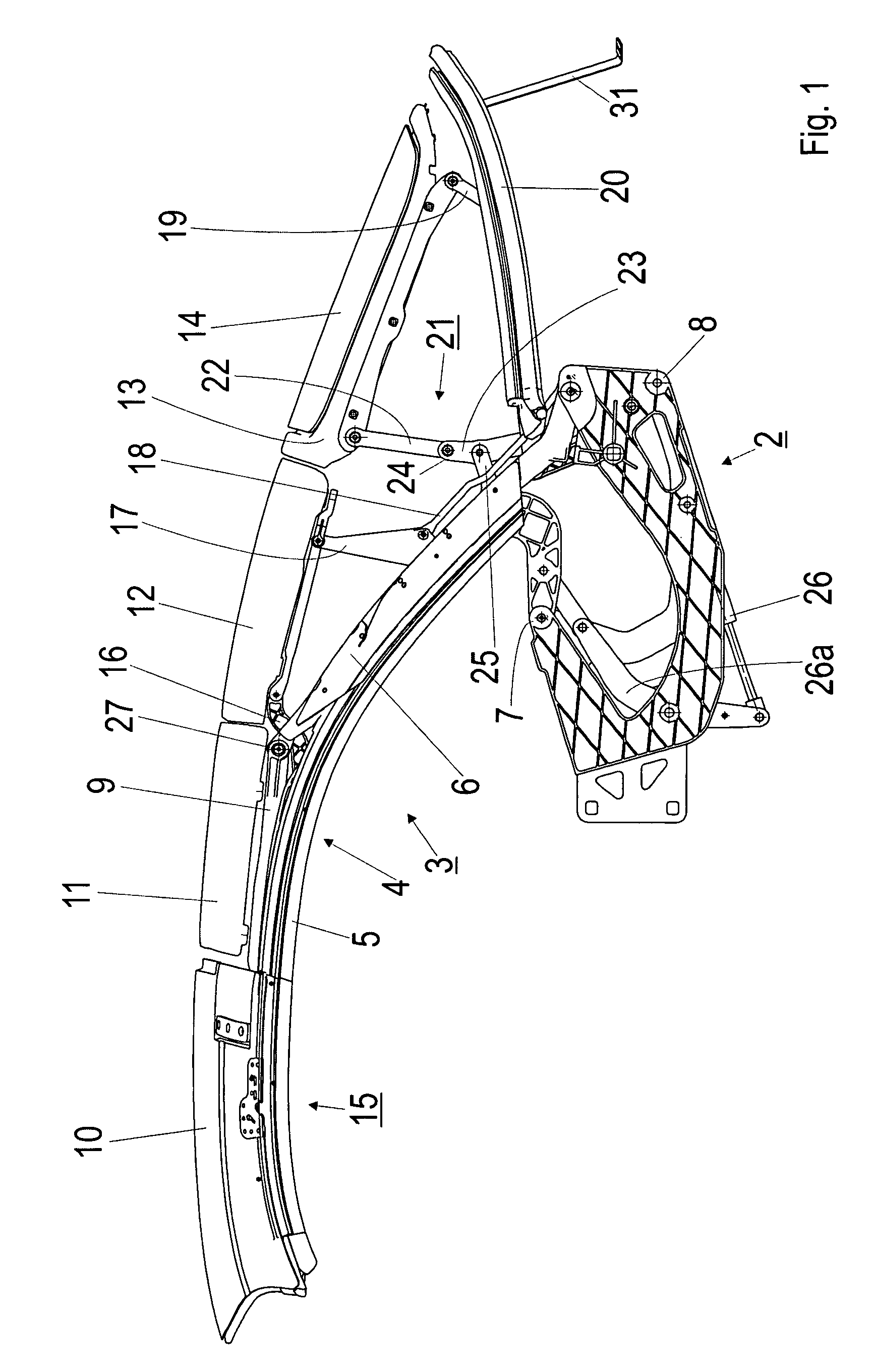
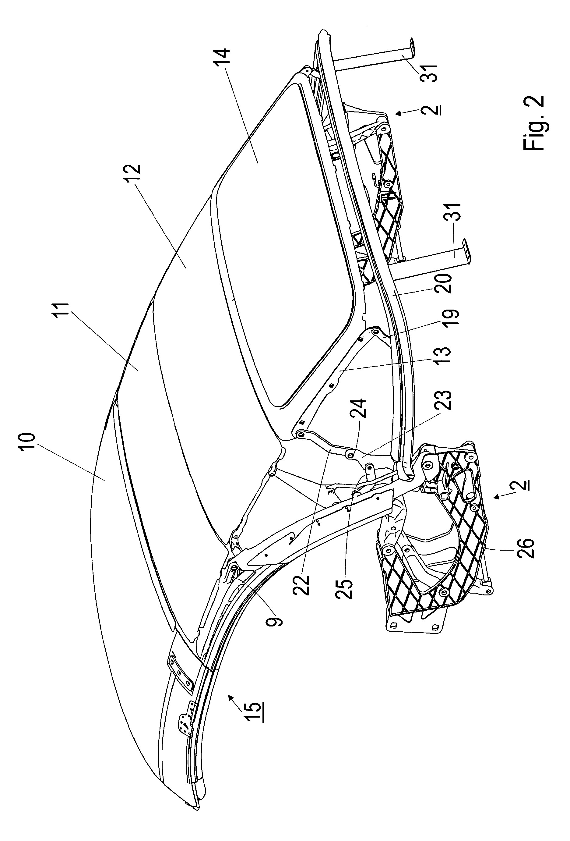
[0047]A top according to the invention is explained in detail below with regard to an operating principle and the associated kinematic structure of the links in a preferred embodiment with reference to FIG. 1 to FIG. 11.

[0048]FIG. 1 shows a top 1 according to the invention in a side view with its essential elements. A main bearing unit 2 to which a main link mechanism 3 is connected in an articulated manner is fastened in a vehicle body (not illustrated). The main link mechanism 3 is designed as a main four-bar linkage 4 which has a front link in the form of a “main pillar”5 and a rear link in the form of a “main link”6. The main pillar 5 and the main link 6 are coupled to the main bearing unit 2 via joint eyes 7, 8 and are connected to each other at their ends opposite the main bearing unit 2 by means of a coupling link 9.

[0049]The top 1 according to the invention comprises a front bow 10, a first surface bow 11, a second surface bow 12 and a rear window frame 13 in which a rear wi...


PUM


Abstract

The invention relates to a top for a convertible, comprising a front bow, a first surface bow, a second surface bow, and a main link mechanism being adapted to displace the front bow, the first surface bow and the second surface bow with respect to a body-mounted main bearing unit in order to open or to close the top, wherein the main link mechanism comprises a main pillar and a main link, wherein, when the top is closed, the front bow, the first surface bow and the second surface bow cover an interior space of the convertible, wherein the first surface bow is arranged between the front bow and the second surface bow, wherein a first supporting link connects the second surface bow in an articulated manner to the main pillar, and wherein a second supporting link connects the second surface bow in an articulated manner to the main link.

Description

[0001]Priority is claimed to German Patent Application 10 2007 051 120.7-24, filed on Oct. 24, 2007, and to German Patent Application 10 2007 051 121.5-24, filed on Oct. 24, 2007, the entire disclosure of which is incorporated by reference herein.BACKGROUND OF THE INVENTION[0002]The invention relates to a top for a convertible in general and in particular in the case of four-seater vehicles, the top comprises at least three rigid roof parts or surface bows in order to be able to completely cover the interior space of the vehicle in the closed state of the top. Diverse forms of convertible tops are known.[0003]DE 100 06 296 C1 shows a top for a convertible vehicle comprising a main roof element and two further roof elements arranged movably thereon. The main roof element is mounted pivotably by means of a link mechanism on a body-mounted main bearing device. During opening of the top from a closed state of the top, the two further roof elements and the main roof element can be arrang...

Claims


Application Information

Patent Timeline
Patent Type & Authority Patents(United States)
IPC IPC(8): B60J7/14B60J7/08
CPCB60J7/146
Inventor HABERL, FRANZKOPP, GEORG
Owner WEBASTO EDSCHA CABRIO
Why Eureka
Eureka Blog
Learn More