Periscopic lifting camera assembly and electronic equipment

A camera and periscope technology, applied in the field of cameras, can solve the problems of slow lifting speed, damage, complex structure, etc., and achieve the effect of avoiding conductive damage, avoiding equipment damage, and fast moving structure

Pending Publication Date: 2019-12-31
深圳市传感技术有限公司
View PDF0 Cites 0 Cited by
  • Summary
  • Abstract
  • Description
  • Claims
  • Application Information

AI Technical Summary

Problems solved by technology

The existing solutions mainly include the following two types: 1. A small hole is opened on the complete display screen or a part of the area is cut off on the complete screen, and the front camera is placed in the small hole or screen gap for video recording. Take pictures; although this method increases the screen-to-body ratio of the mobile phone display to a certain extent, it will make the display appear incomplete and lack aesthetics. It is a pseudo-full screen approach
2. Use a stepping motor with springs and gears to drive the camera up and down, or use a slide cover to drive the camera up and down, so that the camera can be extended out of the phone when needed, and hidden inside the phone when it is not needed, so as to solve the problem of the full screen of the phone. Contradictions with the front camera, this implementation often requires the use of a camera with a flexible cable to adapt to the signal transmission and power supply when the camera moves back and forth, and the flexible cable is prone to cable breakage after being folded back and forth, resulting in The damage of the camera, the use of stepping motors, gears, springs and track drives at the same time results in complex structures, slow lifting speeds, high costs and difficult to popularize

Method used


Image

  • Periscopic lifting camera assembly and electronic equipment
  • Periscopic lifting camera assembly and electronic equipment
  • Periscopic lifting camera assembly and electronic equipment

Examples


Embodiment 1

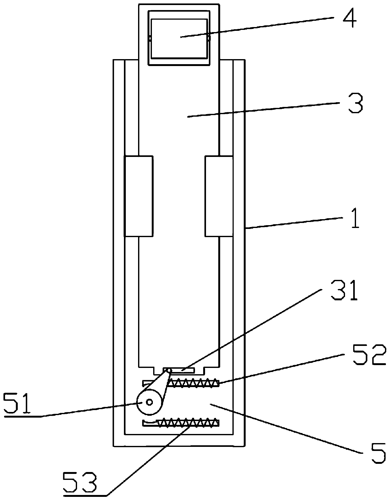
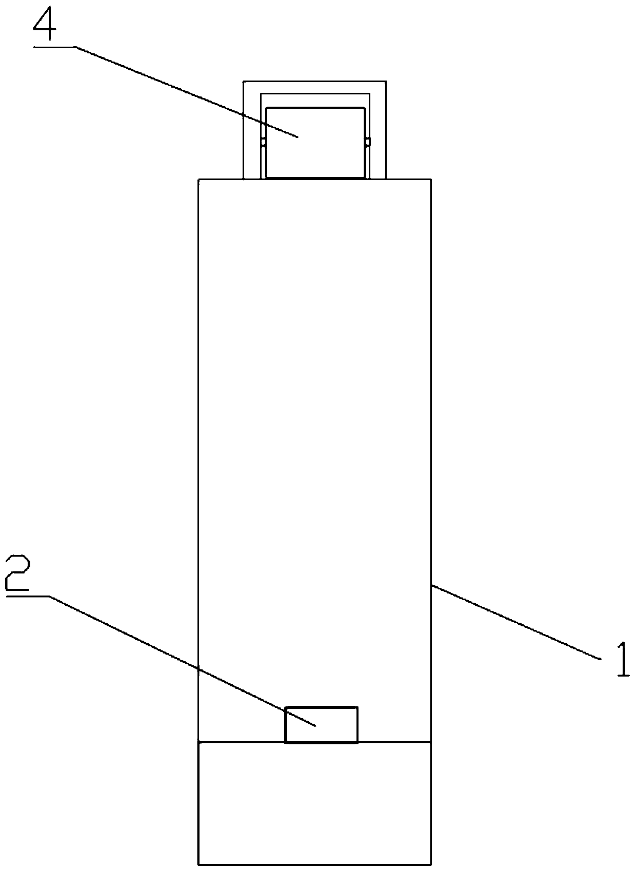
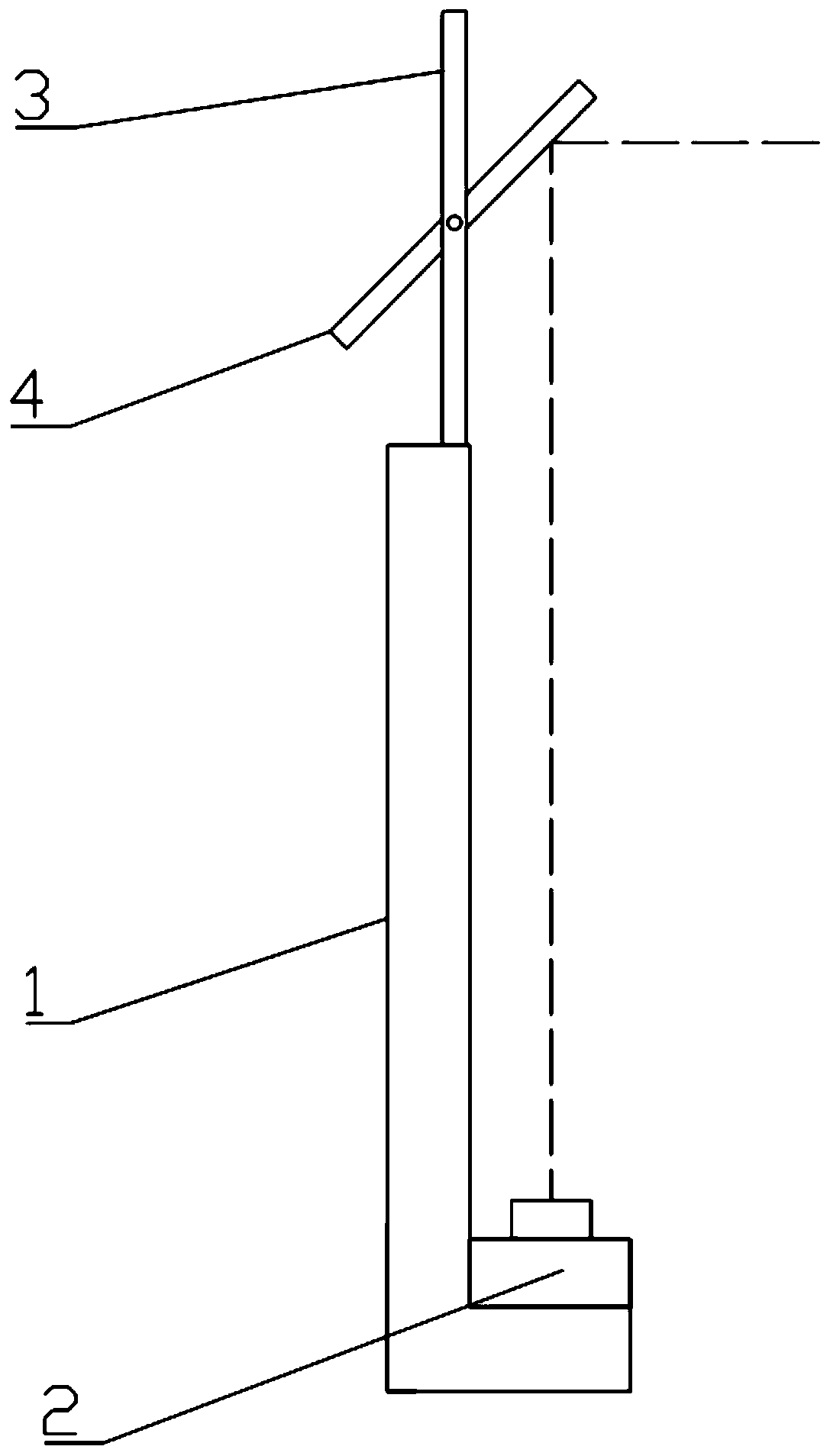
[0031] Such as figure 1 and figure 2 As shown, the periscope lifting camera assembly provided by Embodiment 1 of the present invention includes a base 1 , a camera 2 , a moving piece 3 , a first reflective piece 4 and a first magnetic drive device 5 . The base 1 is in the shape of a cuboid as a whole, and its upper end and front end are opened and formed with grooves. The moving piece 3 is a rectangular plate whose shape and size match the groove, so that it can be placed in the groove and move up and down freely. In order to keep the moving piece 3 moving more stably in the groove, there are vertically parallel sliding grooves on both sides of the groove in this embodiment. Avoid offsetting its movement path. A boss is provided at the bottom of the rear end of the base 1, and the camera 2 is mounted on the boss facing upwards. Such as image 3 As shown, the first reflective sheet 4 is installed on the upper end of the movable sheet 3, and it is inclined at a certain ang...

Embodiment 2

[0036] Compared with embodiment one, embodiment two differs in that: as Figure 10 As shown, the camera 2 is installed obliquely at a certain angle. The periscope lifting camera assembly also includes a second reflective sheet 6 installed on the base 1. The light reflected by the first reflective sheet 4 is reflected twice by the second reflective sheet 6. Enter 2. This installation method makes the thickness occupied by the camera smaller, which is conducive to reducing the thickness of the camera installed on the device when the camera assembly is installed on the electronic device, so that the electronic device can be made thinner. The periscope lifting camera assembly also includes an inductive obstacle avoidance device connected to the first magnetic force drive device, and the inductive obstacle avoidance device is used to send a signal to the first magnetic force drive device when an obstacle occurs above the moving sheet 3, so that the first magnetic force drive The d...


PUM


Abstract

The invention relates to a periscopic lifting camera assembly and electronic equipment. The periscopic lifting camera assembly comprises a base, a camera mounted at the lower end of the base, a movingsheet connected with the base in a sliding sleeve fit manner, a first reflective sheet mounted at the upper end of the moving sheet, and a first magnetic driving device for driving the moving sheet to move up and down; the first reflective sheet is obliquely arranged at a certain angle, and the front light rays of the first reflective sheet can be downwards reflected; and a lens of the camera isaligned with the first reflective sheet, so that the light reflected by the first reflective sheet can be completely shined into the camera, the first magnetic force driving device can drive the moving piece to move upwards to enable the first reflective sheet to completely extend out of the base, and can drive the moving piece to move downwards to enable the first reflective sheet to be completely hidden in the base.

Description

technical field [0001] The invention relates to the field of cameras, in particular to a periscope lifting camera assembly and electronic equipment. Background technique [0002] The display screen of smartphones is getting closer to full screen, and the front camera of smartphones often becomes an obstacle to enlarge the display ratio of mobile phones. The existing solutions mainly include the following two types: 1. A small hole is opened on the complete display screen or a part of the area is cut off on the complete screen, and the front camera is placed in the small hole or screen gap for video recording. Take pictures; although this method increases the screen-to-body ratio of the mobile phone display to a certain extent, it will make the display appear incomplete and lack aesthetics. It is a pseudo-full screen approach. 2. Use a stepping motor with springs and gears to drive the camera up and down, or use a slide cover to drive the camera up and down, so that the came...

Claims


Application Information

Patent Timeline
Patent Type & Authority Applications(China)
IPC IPC(8): H04N5/225H04M1/02
CPCH04M1/0264H04N23/50H04N23/57
Inventor 胡兴超
Owner 深圳市传感技术有限公司
Why Eureka
Try Eureka