Rotating platform for potted plants

Inactive Publication Date: 2012-05-01
DUFF SR THOMAS A
View PDF15 Cites 18 Cited by
  • Summary
  • Abstract
  • Description
  • Claims
  • Application Information

AI Technical Summary

Benefits of technology

[0007]In view of the foregoing references, the inventor recognized the aforementioned inherent problems and observed that there is a need for a platform for potted plants that provides a means for automatically rotating the plant so sunlight is evenly distributed, thus reducing the uneven growth ordinarily seen in indoor plants while also providing a decorative display platform and as such, the object of the present invention is to provide for this need.
[0012]Yet still another object of the rotating base for potted house plants is to provide a slidingly attached solar power panel comprising a horizontal slide mechanism which engages the base and provides a means of housing the solar panel within the base when not needed and deploying the solar panel outwardly from the base to increase the available sunlight which can be obstructed near the base due to the hanging foliage of the plant.
[0016]Yet still another object of the rotating base for potted house plants is to provide a method of utilizing the device that enables completely straight plant growth without the manual turning of plants away from the light in a unique and novel and manner.

Problems solved by technology

High concentrations of auxin cause stem cells to grow more rapidly and elongate and its absence causes cells to grow more slowly and shorten.
This causes a stem to grow unevenly, the side away from the light grows more rapidly than the side toward the light and as a result, the stem begins to bend.
Since the sun regulates the schedule of plant growth, even if the plants are rotated on a daily basis, they can still have a skewed look and achieve an unhealthy growth pattern.
While these devices fulfill their respective, particular objectives, each of these references suffers from one (1) or more of the deficiencies and disadvantages by failing to provide a practical and efficient means of automatically rotating a potted plant which doesn't require regular attention and maintenance to be effective.

Method used


Image

  • Rotating platform for potted plants
  • Rotating platform for potted plants
  • Rotating platform for potted plants

Examples


Embodiment Construction

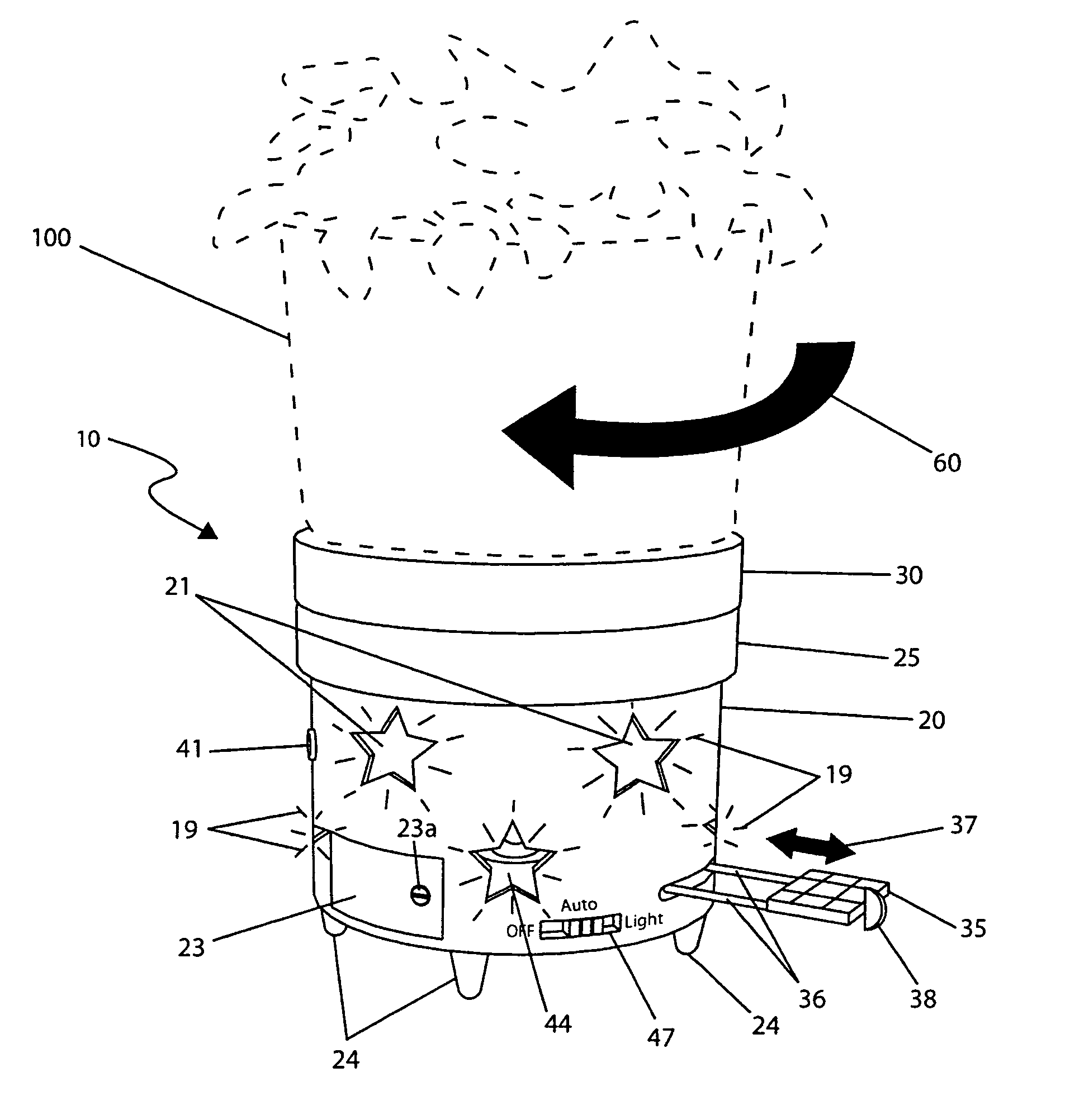
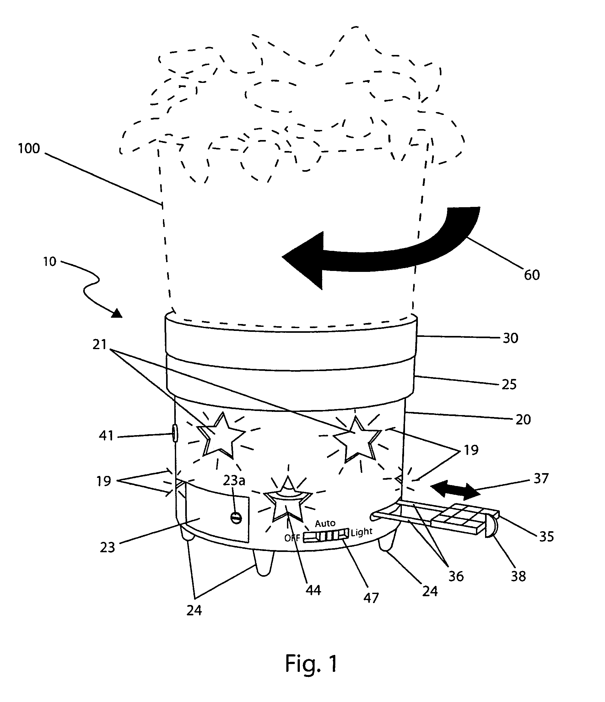
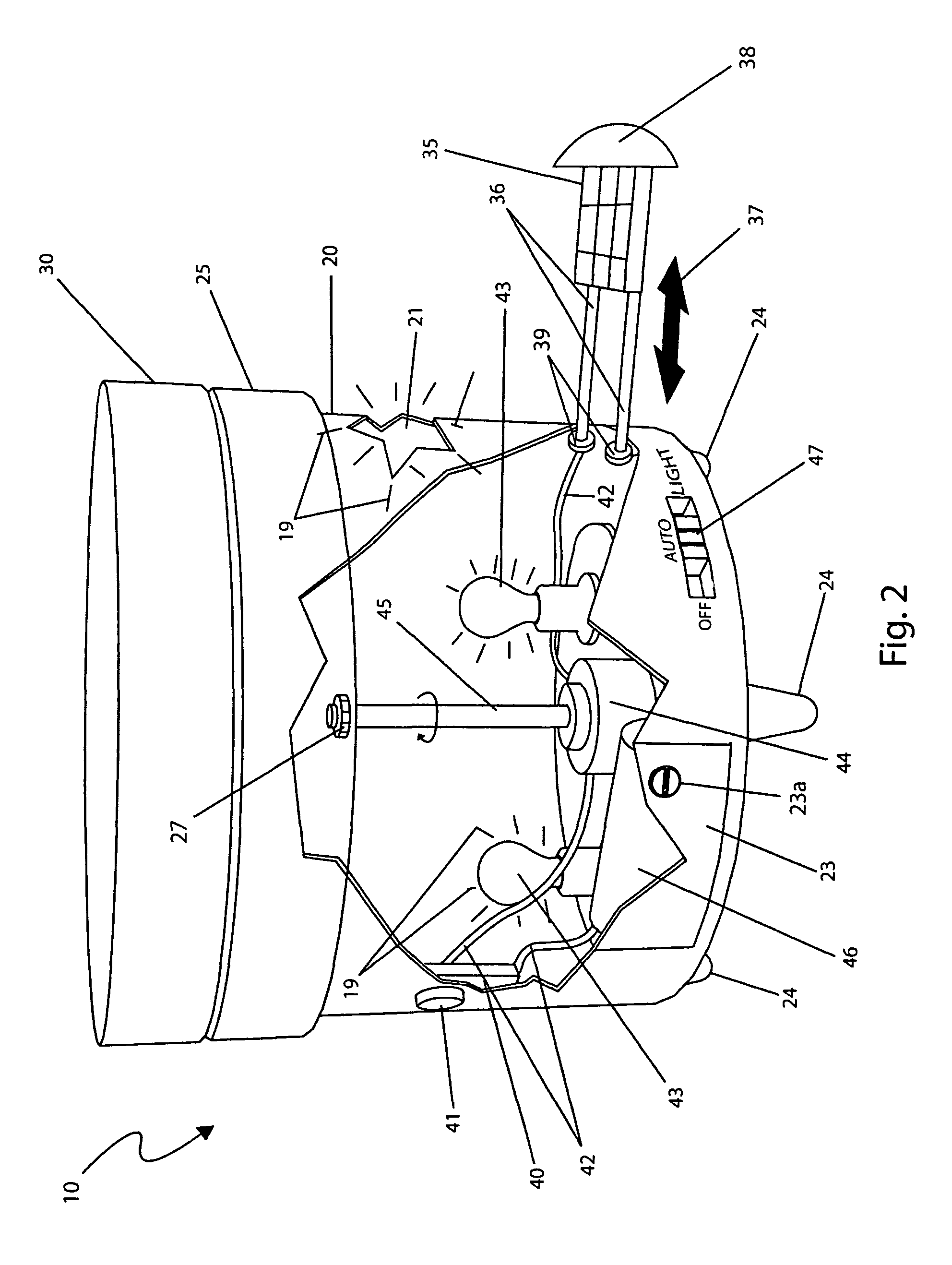
[0026]The best mode for carrying out the invention is presented in terms of its preferred embodiment, herein depicted within FIGS. 1 through 3 and alternately within FIGS. 4 through 6. However, the invention is not limited to the described embodiment, and a person skilled in the art will appreciate that many other embodiments of the invention are possible without deviating from the basic concept of the invention, and that any such work around will also fall under scope of this invention. It is envisioned that other styles and configurations of the present invention can be easily incorporated into the teachings of the present invention, and only one particular configuration shall be shown and described for purposes of clarity and disclosure and not by way of limitation of scope.

[0027]The terms “a” and “an” herein do not denote a limitation of quantity, but rather denote the presence of at least one of the referenced items.

[0028]The present invention describes a rotating platform for ...


PUM


Abstract

A rotating base for house plant planters is herein disclosed, wherein said base slowly turns to complete a revolution within a pre-determined period, to urge the plant in the planter to grow in a vertical direction. The planter base is powered by a battery which is charged using a solar panel, thereby providing a completely self-contained and maintenance free rotating base and a light sensor causing rotation of the planter base only when light is present. The planter base is available in multiple sizes to fit all sizes of pots and planters.

Description

RELATED APPLICATIONS[0001]The present invention was first described in and claims the benefit of U.S. Provisional Application No. 61 / 128,756, filed May 27, 2008, the entire disclosures of which are incorporated herein by reference.FIELD OF THE INVENTION[0002]The present invention relates generally to potted plant platforms, and more particularly, to an automatically rotating platform for potted plants.BACKGROUND OF THE INVENTION[0003]Plants and flowers are a welcome addition to any décor. Their vibrant colors combined with their unique physical traits and pleasant aromas often form the centerpiece of a home or garden. As with most living things, plants and flowers require attentive care for them to achieve their full potential. This of course includes many tasks, such as pruning, feeding and watering. One (1) additional common task is the manual rotation of the plant on a daily basis to prevent the plant from becoming permanently skewed due to growing towards the light. This movemen...

Claims


Application Information

Patent Timeline
IPC IPC(8): A47G7/00
CPCA47G7/041A47G2200/08
Inventor DUFF, SR., THOMAS A.
Owner DUFF SR THOMAS A
Why Eureka
Try Eureka