
Housing assembly for a portable electronic device

a portable electronic device and housing technology, applied in the direction of electrical apparatus casings/cabinets/drawers, electrical apparatus construction details, instruments, etc., can solve the problems of inconvenient type of assembly, inability to provide a proper housing assembly, and screw disengagement from parts easily, etc., to achieve convenient replacement, quick assembly and manufacturing, and low cost

Active Publication Date: 2012-04-24
KING SLIDE WORKS CO LTD
View PDF5 Cites 39 Cited by
  • Summary
  • Abstract
  • Description
  • Claims
  • Application Information

AI Technical Summary

Benefits of technology

[0007]The present invention intends to provide a housing assembly for a portable electronic device and the housing assembly can be quickly assembled and manufactured at low cost, the users can conveniently replace the housings of the housing assembly.

Problems solved by technology

However, it is a time consuming task to install the screws one by one and once the threads of the holes in the parts of the housing assembly are rounded or damaged, the screws can easily disengage from the parts.
However, when disengaging these protrusions, the parts are separated so that this type of assembly is not suitable for the housing assembly that allows the user to replace a single part.
All of the prior arts mentioned above cannot provide a proper housing assembly that allows the users to quickly disengage the parts of the housing assembly for electronic devices.

Method used


Image

  • Housing assembly for a portable electronic device
  • Housing assembly for a portable electronic device
  • Housing assembly for a portable electronic device

Examples


first embodiment

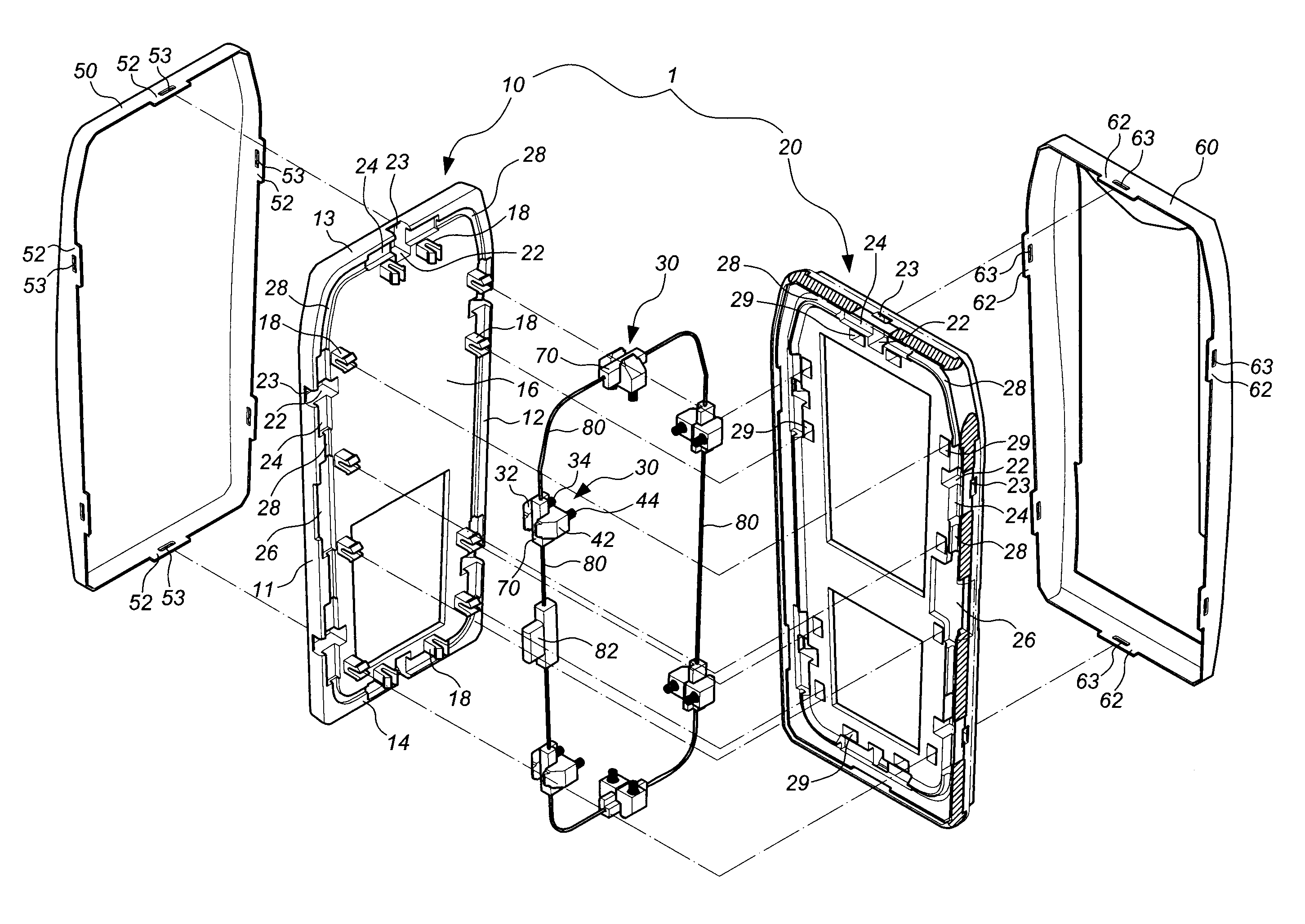
[0043]Referring to FIGS. 1 to 3, a housing assembly according to the present invention comprises a mounting assembly 1, multiple engaging assemblies 30, a first housing 50, a second housing 60, multiple guiding members 70, and a connection member 80.

[0044]The mounting assembly 1 has a first part 10 and a second part 20 which is connected to the first part 10. The first part 10 includes a first wall 11, a second wall 12 located corresponding to the first wall 11, a third wall 13 connected between the first and second walls 11, 12, and a fourth wall 14 located corresponding to the third wall 13 and connected between the first and second walls 11, 12. The first and second walls 11, 12 are located on two sides of the first part 10 and the third and fourth walls 13, 14 are located on two ends of the first part 10. A board 16 is connected with the first, second, third and fourth walls 11, 12, 13, 14, and multiple lugs 18 extend from the board 16. The second part 20 and the first to fourth...

fourth embodiment

[0053]FIGS. 14 to 16 show the present invention, which includes a first engaging member 32c and a second engaging member 42c. The first and second engaging members 32c, 42c include first and second guiding slots 33c, 43c and first and second force receiving portions 36c, 46c, respectively. The first force receiving portion 36c tilts towards the same direction as that of the first engaging portion 38c. The second force receiving portion 46c tilts towards the same direction as that of the second engaging portion 48c. A guiding member 70c is movably connected to the connection member 80. As shown in the drawings, the connection member 80 has a connecting block 81 which is movably connected to the guiding member 70c. The guiding member 70c includes a first cam 71c and a second cam 72c. The first cam 71c is located corresponding to the first force receiving portion 36c of the first engaging member 32c, and the second cam 72c is located corresponding to the second force receiving portion ...


PUM


Abstract

A housing assembly for an electronic device includes a mounting assembly, an engaging assembly, a first housing, and a guiding member. The mounting assembly includes an accommodation room having an opening therein. The engaging assembly includes a first elastic member and a first engaging member mounted in the accommodation room. The first engaging member includes a first force receiving portion and a first engaging portion corresponding to the opening. The first housing is coupled with the mounting assembly and includes an assembling portion to be connected with the first engaging portion. The guiding member has a first guiding portion corresponding to the first force receiving portion. When the first guiding portion of the guiding member is applied by a force to move the first force receiving portion of the first engaging member to a position, the first engaging member is disengaged from the assembling portion of the first housing.

Description

FIELD OF THE INVENTION[0001]The present invention relates to a housing assembly, and more particularly, to a housing assembly for a portable electronic device.BACKGROUND OF THE INVENTION[0002]Generally speaking, housing assembly for an electrical device depends on screws to connect the housing assembly together and the quality of assembly for the electrical device, such as the connection between the parts of the housing assembly depends on the proper installation of the screws. However, it is a time consuming task to install the screws one by one and once the threads of the holes in the parts of the housing assembly are rounded or damaged, the screws can easily disengage from the parts. Therefore, another improved housing assembly for an electrical device is developed.[0003]U.S. Pat. No. 5,946,395 to Petrella et al., discloses a “Housing assembly for an electronic device”, U.S. Pat. No. 7,116,780 to Sun, discloses a “Housing assembly for a portable electronic device”, and U.S. Pat. ...

Claims


Application Information

Patent Timeline
Patent Type & Authority Patents(United States)
IPC IPC(8): G06F1/16H04B1/38H04M1/00
CPCH04M1/0249H04M1/0252Y02P20/141
Inventor CHEN, JUNG-PINLIN, SHU-CHENCHEN, SHAN-YAO
Owner KING SLIDE WORKS CO LTD
Learn More