Loudspeaker array system

a loudspeaker array and loudspeaker technology, applied in the direction of tone control, transducer casing/cabinet/support, electric transducer, etc., can solve the problems of more acoustic problems, difficult to achieve such a high-quality sound across a wide frequency range, etc., and achieve the effect of high-quality sound

Inactive Publication Date: 2012-04-17
APPLE INC
View PDF16 Cites 10 Cited by
  • Summary
  • Abstract
  • Description
  • Claims
  • Application Information

AI Technical Summary

Benefits of technology

[0012]The invention is a multi-way array loudspeaker that can produce high-quality sound in high fidelity stereo systems, multi-channel home entertainment systems or public address systems.
[0016]The multi-way loudspeaker system may employ drivers of different sizes, producing low distortion, high-power handling because specialized drivers can operate optimal in their dedicated frequency band, as opposed to arrays of identical wide-band drivers. The multi-way speaker design of the invention can also provide better control of in-room responses due to smooth out-of-axis responses. The system is further able to control the frequency response of reflected sound, as well as the total sound power, and to suppress floor and ceiling reflections.

Problems solved by technology

Achieving such a high quality sound across a wide frequency range has been challenging due to the variation in size of the transducers across the dedicated parts of the audio frequency band and the constraints in spacing between the transducers.
However, because of the physical sizes of the specialized drivers, the ability to position the drivers in close proximity to one another is limited.
The farther the drivers are positioned from one another, the more acoustic problems arise.
However, the use of uniform coverage horns has its disadvantages, as the uniform coverage horns have a limited frequency range, fixed, non-steerable polar patterns, and relatively high distortion.
However, since the drivers in the two-dimensional, linearly spaced arrays are identical, the maximum sound pressure level, and sound quality of the sound projector is limited to the capabilities of the transducers, which is in general rather poor, compared with drive units that are optimized for a dedicated frequency band.
Further, the sound projector employs a very high number of drivers that all need to be driven individually, which leads to high implementation complexity and high cost.

Method used


Image

  • Loudspeaker array system
  • Loudspeaker array system
  • Loudspeaker array system

Examples


Embodiment Construction

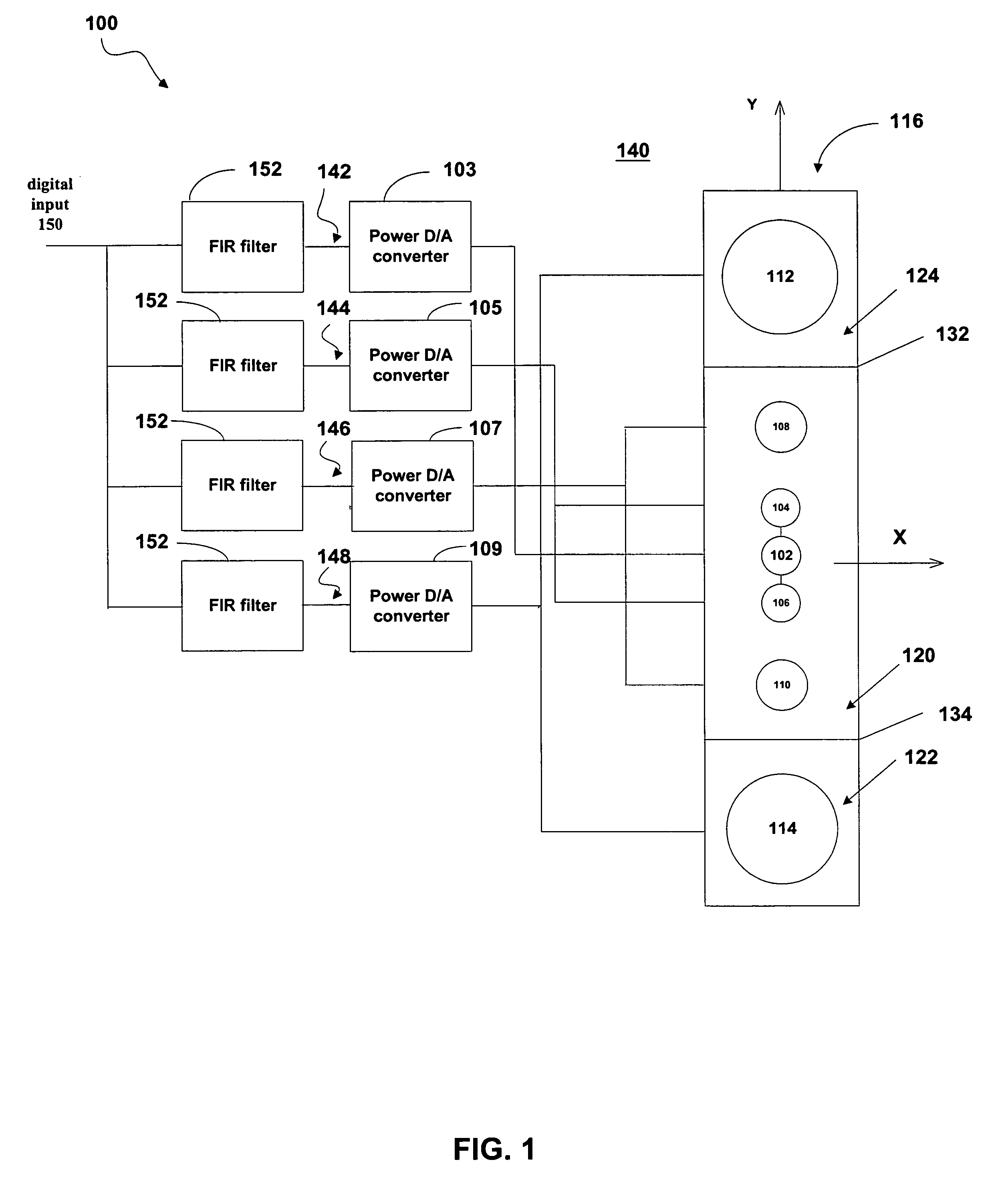
[0041]FIG. 1 illustrates an example implementation of a one-dimensional (1D) multi-way loudspeaker 100 which forms the bases of the invention and a block diagram of the signal flow to each of the loudspeaker drivers in the system 100. As shown in FIG. 1, the multi-way loudspeaker 100 may be designed as a four-way loudspeaker having (i) a center tweeter 102 connected to a first power D / A converter 103, (ii) two additional tweeters 104 and 106 connected to a second power D / A converter 105, (iii) two midrange drivers 108 and 110 connected to a third power D / A converter 107, and (v) two woofers 112 and 114 connected to a fourth power D / A converter 109. The connection between the loudspeakers to each amplifier represents a different way in the multi-way loudspeaker.

[0042]In FIG. 1, the drivers, also referred to as transducers, may be mounted in a housing 116 comprised of separate sealed compartments 120, 122, and 124, as indicated by separators 132 and 134. By mounting the drivers in sep...


PUM


Abstract

The invention is a multi-channel loudspeaker system that provides a compact loudspeaker configuration and filter design methodology that operates in the digital signal processing domain. Further, the loudspeaker system can be designed as a multi-way loudspeaker system comprised of a symmetric arrangement of loudspeaker drivers in a two-dimensional plane and can achieve high-quality sound, constant directivity over a large area in both the vertical and horizontal planes and can be used in connection with stereo loudspeaker systems, multi-channel home entertainment systems and public address systems.

Description

CROSS-REFERENCE TO RELATED APPLICATIONS[0001]This application is a continuation-in-part of U.S. patent application Ser. No. 10 / 771,190 filed on Feb. 2, 2004 titled Loudspeaker Array System, and which is incorporated into this application in its entirety.BACKGROUND OF THE INVENTION[0002]1. Field of the Invention[0003]This invention generally relates to a multi-way loudspeaker system and in particular to a multi-way loudspeaker system comprised of a symmetric arrangement of loudspeaker drivers in a two-dimensional plane capable of achieving high-quality sound for use in connection with stereo loudspeaker systems, multi-channel home entertainment systems and public address systems.[0004]2. Related Art[0005]Loudspeaker designers are constantly striving to design controlled directivity loudspeaker systems that achieve high quality sound across a wide range of frequency bands while limiting the size and number of transducers (i.e. drivers) in the system, as well as the required number of ...

Claims


Application Information

Patent Timeline
Patent Type & Authority Patents(United States)
IPC IPC(8): H04R1/02H03G5/00H04R5/02H04R1/24H04R1/26H04R1/32H04R3/00H04R3/12H04R31/00
CPCH04R1/26H04R25/405H04R5/02
Inventor HORBACH, ULRICH
Owner APPLE INC
Why Eureka
Try Eureka