
Lifting and positioning apparatus

a technology for positioning apparatus and lifting load, which is applied in the field of lifting load apparatus, can solve the problems of difficult manoeuvre, inability to adjust the horizontal plane position of the load using such apparatus, etc., and achieve the effect of simplifying the construction process and facilitating the positioning of the heavy load

Inactive Publication Date: 2012-04-10
GRAHAM GEOFF
View PDF19 Cites 13 Cited by
  • Summary
  • Abstract
  • Description
  • Claims
  • Application Information

AI Technical Summary

Benefits of technology

"The present invention provides a lifting and positioning apparatus for heavy or bulky loads. The apparatus includes a base support, an elevator mechanism, and a positioning component mounted on the elevator mechanism. The positioning component can provide horizontal linear motion backwards and forwards in a first direction, horizontal linear motion backwards and forwards in a second direction, and horizontal rotation. The apparatus can be easily transported and used to position heavy loads, simplifying the construction process. The technical effects of the invention include improved load lifting and positioning capabilities, simplified construction process, and reduced risk of injury during lifting and positioning operations."

Problems solved by technology

It is generally not possible however, to adjust the position of the load on the horizontal plane using such apparatus.
The lift apparatus therefore provides for elevation of heavy and / or bulky loads in addition to limited adjustment on the horizontal plane, that is, movement of the entire apparatus at ground level.
It is generally not possible, however to adjust the position of the load once it has been elevated.
Whilst apparatus such as pulley arrangements and scissor lift platforms are useful in elevating heavy loads, they are generally difficult to manoeuvre and as such do not facilitate the positioning of a heavy load where it is required.
This can make installation of heavy and / or bulky structures, such as for example fitting a roller door to a bracket secured at an elevated position, difficult.

Method used


Image

  • Lifting and positioning apparatus
  • Lifting and positioning apparatus
  • Lifting and positioning apparatus

Examples


Embodiment Construction

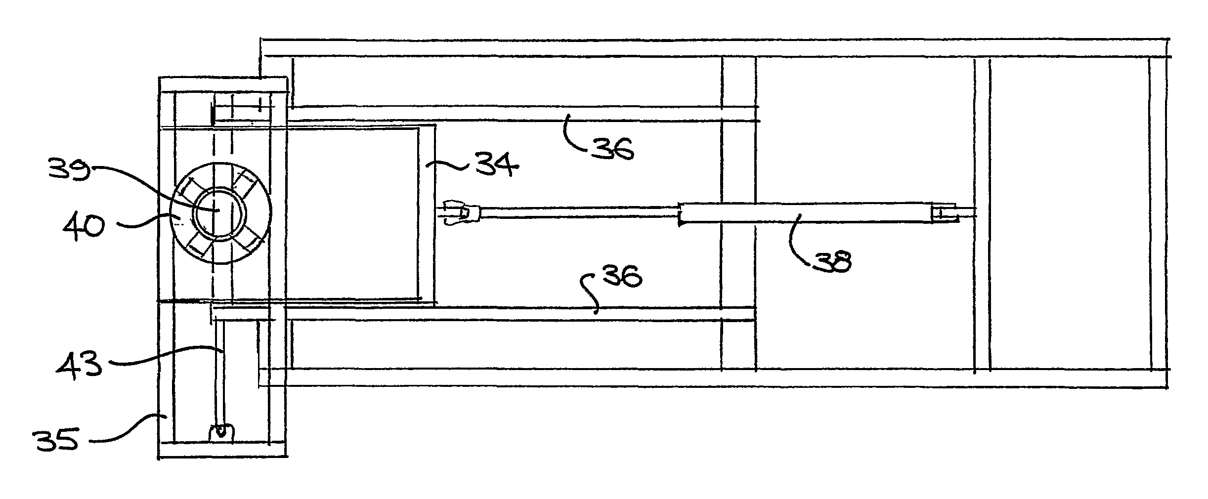
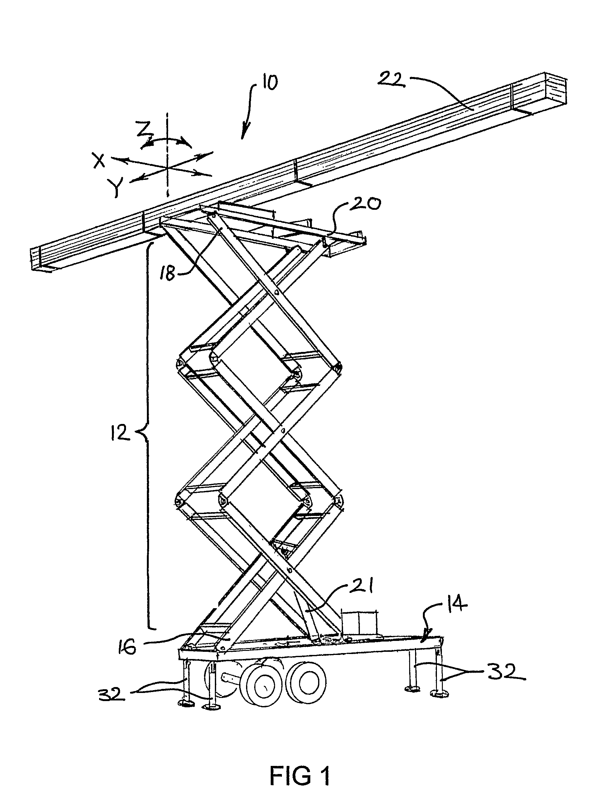
[0036]Referring firstly to FIG. 1, the invention provides a lifting and positioning apparatus 10 including an elevator mechanism 12 carried on a base support 14. A lower end 16 of the elevator mechanism 12 rests on the base support 14 and an upper end 18 of the elevator mechanism 12 supports a positioning component 20.

[0037]An actuator 21 operates the elevator mechanism 12 between a collapsed position (see FIGS. 2A and 3) and a raised operating position (see FIGS. 1, 4A and 5A). In the operating position, the positioning component 20 may be actuated to provide horizontal linear motion backwards and forwards in a first direction X, horizontal linear motion backwards and forwards in a second direction Y, and horizontal rotation Z. In combination these movements facilitate maneuvering of a heavy load 22 such as a roller door when the elevator means 12 is in the operating position.

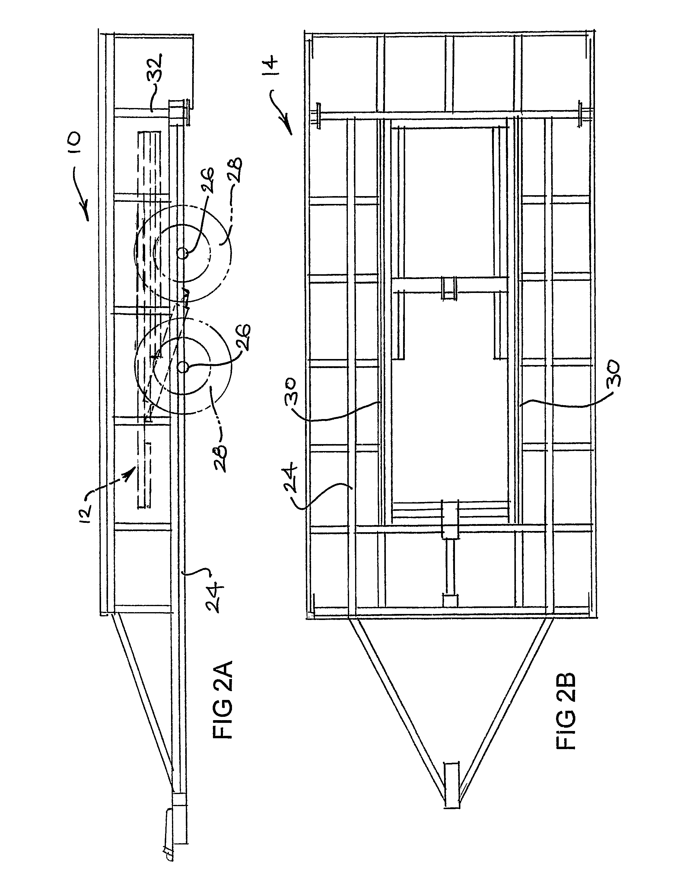
[0038]Referring now to FIGS. 2A and 2B, the base support 14 includes a chassis 24 mounted on two axles 26 w...


PUM


Abstract

A lifting and positioning apparatus (10) including a base support (14), an elevator mechanism (12) having an upper and a lower end; an actuator (21) for operating the elevator mechanism between a collapsed and a raised operating position; and a positioning component (20) mounted on the upper end of the elevator mechanism providing for horizontal linear motion backwards and forwards in a first direction (X), horizontal linear motion backwards and forwards in a second direction (Y), and horizontal rotation (Z).

Description

[0001]This is a national phase application in the United States of International Application CT / AU2006 / 000216 filed 21 Feb. 2006, claiming priority from Australian application number 2005900797 filed 21 Feb. 2005, the disclosures of which are incorporated herein by reference.FIELD OF THE PRESENT INVENTION[0002]The present invention relates generally to an apparatus for lifting loads. The invention relates more particularly to an apparatus for lifting and adjusting the position of a load to facilitate installation of heavy and / or bulky structures.BACKGROUND TO THE INVENTION[0003]Maintenance and construction of buildings and similar tall structures often involves lifting of heavy and / or bulky loads such as beams, trusses, guttering, roller doors and the like. Various apparatus is available to enable such loads to be lifted to elevated areas. Such devices include block and tackle arrangements, hoists, and scissors lift platform apparatus.[0004]A block and tackle arrangement or similar ...

Claims


Application Information

Patent Timeline
Patent Type & Authority Patents(United States)
IPC IPC(8): E06C5/00
CPCB66F7/0625B66F7/28B66F7/08B66F7/0666
Inventor GRAHAM, GEOFF
Owner GRAHAM GEOFF
Learn More