
Method for monitoring whether the switching threshold of a switching transducer lies within a predefined tolerance range

a technology of switching transducer and threshold, which is applied in the direction of electrical testing, instruments, electrical apparatus, etc., can solve the problems of software errors, program crashes, and affecting the operation sequence, and achieve the effect of reducing the risk of undiscovered failures

Inactive Publication Date: 2012-04-03
PEPPERL FUCHS GMBH
View PDF3 Cites 2 Cited by
  • Summary
  • Abstract
  • Description
  • Claims
  • Application Information

AI Technical Summary

Benefits of technology

[0008]The invention is based on the objective of putting forward a method with which it is possible to monitor whether the switching threshold of a switching transducer lies within a tolerance range, whereby the method should especially be useable for monitoring an electrical signal for drift as well as for monitoring the switching threshold for drift in switching procedures of the above-mentioned type, especially in the case of switching procedures that make use of components in which the drift of electric parameters cannot or must not be ruled out, and also for reducing the risk of undiscovered failures in switching devices.
[0014]In an advantageous manner, the invention puts forward a method with which it is possible to monitor whether the switching threshold of a switching transducer lies within a tolerance range. Here, the method is especially useable for monitoring an electrical signal for drift as well as for monitoring the switching threshold for drift in switching procedures of the above-mentioned type, especially in the case of switching procedures that make use of components in which the drift of electric parameters cannot or must not be ruled out. By the same token, the risk of undiscovered failures in switching devices is reduced.
[0118]The invention makes it possible to meet the requirement of safety standards that call for the safety-oriented determination of switching thresholds and can thus ensure the compatibility between safety-oriented switching devices.

Problems solved by technology

These examples already show that malfunctions with such switching procedures can not only disrupt an operational sequence but also endanger considerable material values and especially the safety of humans.
During such switching procedures, malfunctions can be caused especially in that the threshold value moves away from a target value without being noticed, i.e. drifts uncontrolled.
Such a switching threshold drift can be the result of, for example, temperature fluctuations, ageing, dirt, wear and tear, or production flaws in components; in the case of systems controlled by computers or microprocessors, the possible causes can also include software errors and program crashes.

Method used


Image

  • Method for monitoring whether the switching threshold of a switching transducer lies within a predefined tolerance range
  • Method for monitoring whether the switching threshold of a switching transducer lies within a predefined tolerance range
  • Method for monitoring whether the switching threshold of a switching transducer lies within a predefined tolerance range

Examples


Embodiment Construction

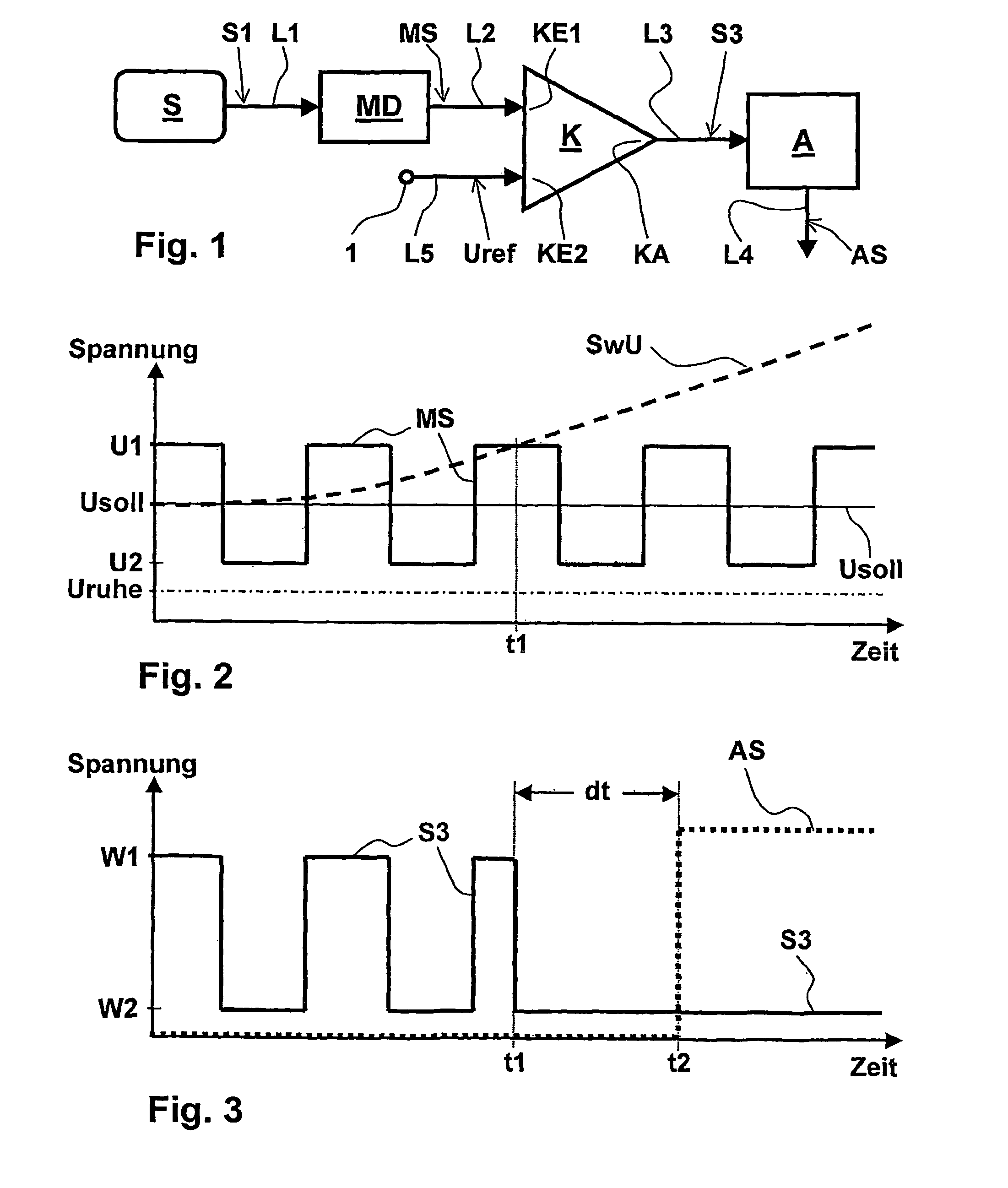
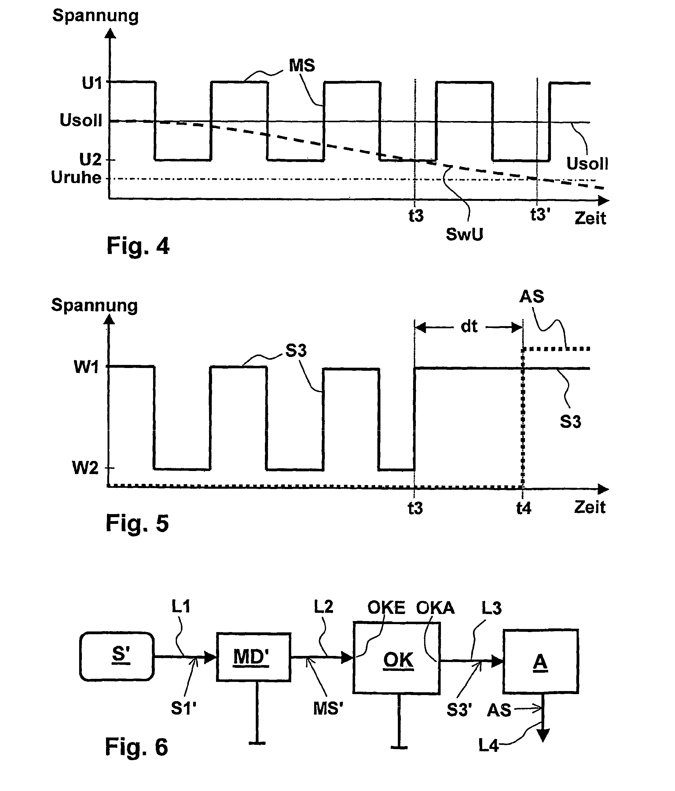
[0141]First of all, reference will be made to FIGS. 1 to 5. FIG. 1 shows a block diagram of a circuit for executing the method according to the invention. The circuit shown in FIG. 1 serves for the inventive monitoring of the switching threshold of a comparator K for deviation from a target value, said circuit also comprising a signal source S, an evaluation unit A and a modulator MD. The comparator K has a signal input KE1, a reference input KE2 and a switching output KA.

[0142]In principle, any direct-voltage source, for instance, a battery or an in-phase regulator, can serve as the signal source S. In the example shown in FIG. 1, the signal source S is a sensor S that can be in an activated and in a non-activated state.

[0143]The sensor S can especially be one with a switching output, particularly a proximity sensor that responds when an object approaches and, in this process, changes over from the non-activated state to the activated state. According to another example, the sensor...


PUM


Abstract

A method monitors whether the switching threshold of a switching sensor lies within a predefined tolerance region. An input signal is applied to the sensor's signal input, and a signal output emits a switch output signal that takes a first value when the input signal exceeds the switching threshold and, otherwise, takes a second value. A modulator generates a modulator signal used as an input signal that changes continuously or cyclically between an output value defining the upper limit and a smaller test value defining the lower limit of the tolerance region. The switch output signal pulses synchronously with the modulator signal between the first and second values when the switching threshold lies within the tolerance region and otherwise does not pulse. An evaluation device monitors the pulsation, an alarm signal being triggered when the switch output signal does not pulse for at least a predefined test period.

Description

CROSS REFERENCE TO RELATED APPLICATIONS[0001]This application is the National Stage of PCT / DE2007 / 001873 filed on Oct. 22, 2007, which claims priority under 35 U.S.C. §119 of German Application No. 10 2006 050 399.6 filed on Oct. 20, 2006 and German Application No. 10 2006 051 312.6 filed Oct. 28, 2006. The international application under PCT article 21(2) was not published in English.BACKGROUND OF THE INVENTION[0002]1. Field of the Invention[0003]The invention relates to a method for monitoring whether the switching threshold of a switching transducer, especially of a comparator, lies within a predefined tolerance range or not.[0004]2. Description of the Related Art[0005]In numerous applications, switching processes take place as a function of measured values or signal quantities. For instance—to name just a few of numerous applications by way of an example—for purposes of the two-point regulation of a temperature, for monitoring the internal pressure in a pressure vessel, for limi...

Claims


Application Information

Patent Timeline
IPC IPC(8): G01R31/02
CPCG01D3/08G01R31/2829G01R31/31932
Inventor HOFMAYER, MATTHIASKINDERMANN, MICHAEL
Owner PEPPERL FUCHS GMBH
Learn More