Ball joint

a ball joint and ball stud technology, applied in the field of ball joints, can solve problems such as looseness, and achieve the effects of preventing and preventing the possibility of co-rotation of the ball stud

Active Publication Date: 2012-03-27
NHK SPRING CO LTD
View PDF23 Cites 2 Cited by
  • Summary
  • Abstract
  • Description
  • Claims
  • Application Information

AI Technical Summary

Benefits of technology

[0009]In accordance with the ball joint of the present invention, because a co-rotation preventing process is applied to the seat surface portion of the ball stud, the co-rotation preventing process works on the mounting member when the nut is fastened, and the ball stud is prevented from co-rotating along with the nut. Accordingly, without leading to an increase in the number of parts and the accompanying troublesomeness of assembly work, the co-rotation of a ball stud can be reliably prevented.
[0010]A specific example of the co-rotation preventing process relating to the present invention is the forming of projections biting into the mounting member in a fastened state. In this case, when the nut is fastened and the seat surface portion is fastened to the mounting member, the projections bite into the mounting member, and the co-rotation of the ball stud is prevented. The projections are preferably a sharp shape easily biting into the mounting member, and when painting is carried out on the mounting member, the co-rotation can be sufficiently prevented in a state in which the projections bite into the paint layer. With respect to the height of the projections, if it is too low, the co-rotation preventing effect is weak, and if it is too high, although co-rotation is prevented, looseness occurs. Therefore, a suitable height is required. For example, when a nut whose stipulated value of screw torque is 40 to 60 N ·m is used, a height of the projection corresponding to this screw torque is suitably 0.03 to 0.12 mm.
[0011]Furthermore, another specific example of the co-rotation preventing process is a surface-roughening process increasing the frictional resistance with respect to the mounting member. The surface-roughening process is for increasing the degree of surface roughness, and with respect to the degree of surface roughness, for example, if co-rotation arises when the degree of surface roughness Ra is about 0.5 to 1.5, by carrying out a surface-roughening process such that Ra is 2.0 or more, the co-rotation can be prevented. As a method of a surface-roughening process, shot peening or the like may be suitably adopted.

Problems solved by technology

With respect to the height of the projections, if it is too low, the co-rotation preventing effect is weak, and if it is too high, although co-rotation is prevented, looseness occurs.

Method used


Image

  • Ball joint
  • Ball joint
  • Ball joint

Examples


examples

[0028]Next, examples of the present invention will be described.

[1] Forming of projections

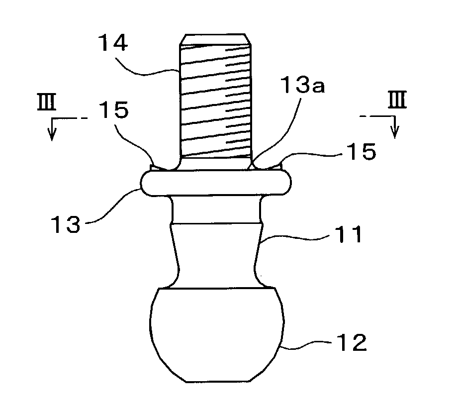
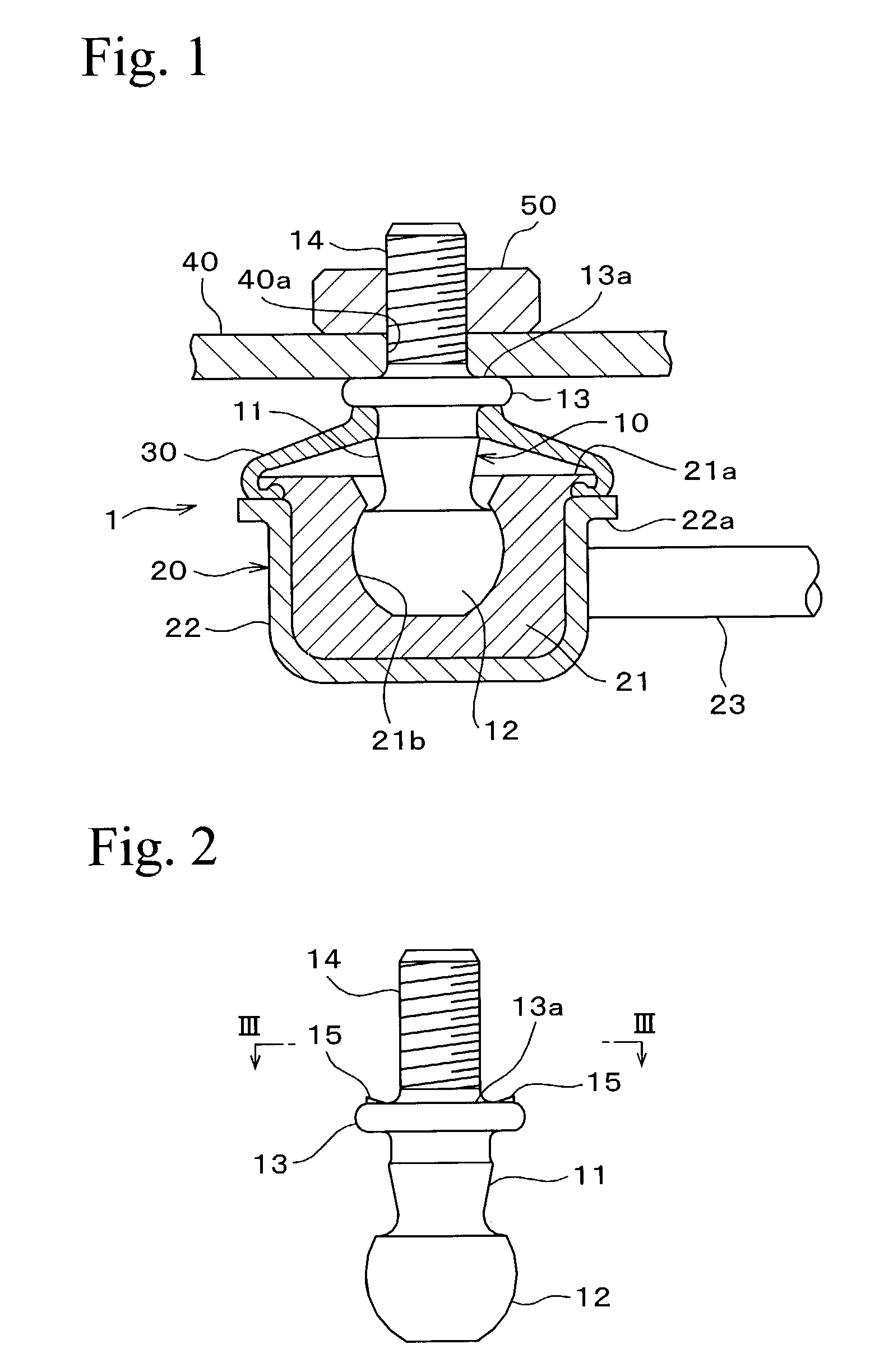
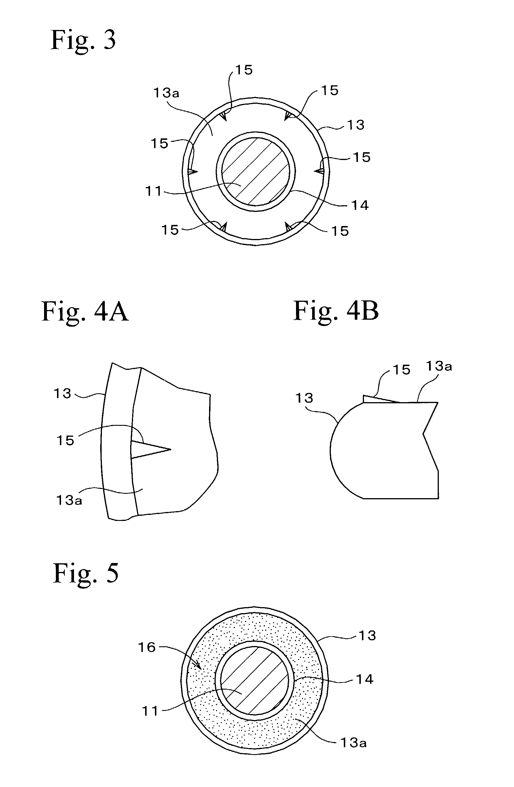
[0029]The projections of the shape and the arrangement shown in FIG. 3 and FIGS. 4A and 4B were formed, while changing the height in a range of 0.01 to 0.16 mm, at a seat surface portion of a collar portion of a ball stud which is the same as the ball stud 10 shown in FIG. 2 and whose material was steel equivalent to S30C to S45C. The projections were formed by forging at the same time as the molding of the ball stud. As shown in FIG. 1, these ball studs were fastened to a mounting member by nuts, and the screw torque when co-rotation arose at the ball stud was investigated. It should be noted that the screw portion with which the nut was screwed was M10, and an electrophoretic coating of a cationic resin was applied at a thickness of 20±10 μm to the surface of the mounting member into which the projections bit.

[0030]FIG. 6 shows the relationship between the height of the projection and co-rota...


PUM


Abstract

A ball joint comprises a ball stud having a stud portion at a middle thereof, a ball portion and a screw portion at opposite sides of the stud portion, and a seat surface portion facing the screw portion between the respective portions, and a bearing member into which the ball portion is slidably fitted so as to universally pivotably-support the ball stud, so that the stud portion is inserted through a mounting member, and a nut is screwed with the screw portion projected from the mounting member, and the seat surface portion abuts and is fastened to the mounting member by fastening the nut to the mounting member. The seat surface portion abutting the mounting member is subjected to a co-rotation preventing process which prevents the ball stud from co-rotating along with the nut when the nut is fastened.

Description

BACKGROUND OF THE INVENTION[0001]1. Field of the Invention[0002]The present invention relates to a ball joint used, for example, at a connection portion of a vehicle stabilizer.[0003]2. Description of the Related Art[0004]Thus type of ball joint is, as disclosed in Japanese Patent Application Laid-Open (JP-A) No. 8-284948, constructed so that a ball portion at one end portion of a ball stud is slidably fitted together with a ball seat and the ball stud is universally pivotably-supported. Furthermore, in order to fix it to a mounting member, the distal end side of the ball stud, at which a screw portion is formed, is passed through the mounting member, and a nut is screwed into the screw portion and fastened. The mounting member is thereby sandwiched by the seat surface portion formed at the ball stud and the nut, and is fastened.[0005]When the nut is fastened and the ball stud is fixed to the mounting member, because the ball stud freely rotates with respect to the ball seat, if the...

Claims


Application Information

Patent Timeline
Patent Type & Authority Patents(United States)
IPC IPC(8): F16C11/06
CPCF16C11/0604F16C11/0619B60G2204/1224B60G2204/416B60G2204/422Y10T403/32631Y10T403/32311B60G2206/11
Inventor OHMURA, SHUJIKURODA, SHIGERUUEDA, MASANAO
Owner NHK SPRING CO LTD
Why Eureka
Try Eureka