
Short circuit protection circuit

a short-circuit protection and relay technology, applied in emergency protective circuit arrangements, relays, electrical equipment, etc., can solve the problems of excessive short-circuit current flow, damage to the relay drive circuit, and accumulation of heat generated by short-circuit curren

Active Publication Date: 2012-03-20
KK TOKAI RIKA DENKI SEISAKUSHO
View PDF12 Cites 8 Cited by
  • Summary
  • Abstract
  • Description
  • Claims
  • Application Information

AI Technical Summary

Benefits of technology

[0010]The present invention provides a short circuit protection circuit and a short circuit protection method that prevents a relay drive circuit from being damaged by a short circuit while readily recovering the relay drive circuit to an output operation state after a short circuit is cancelled.
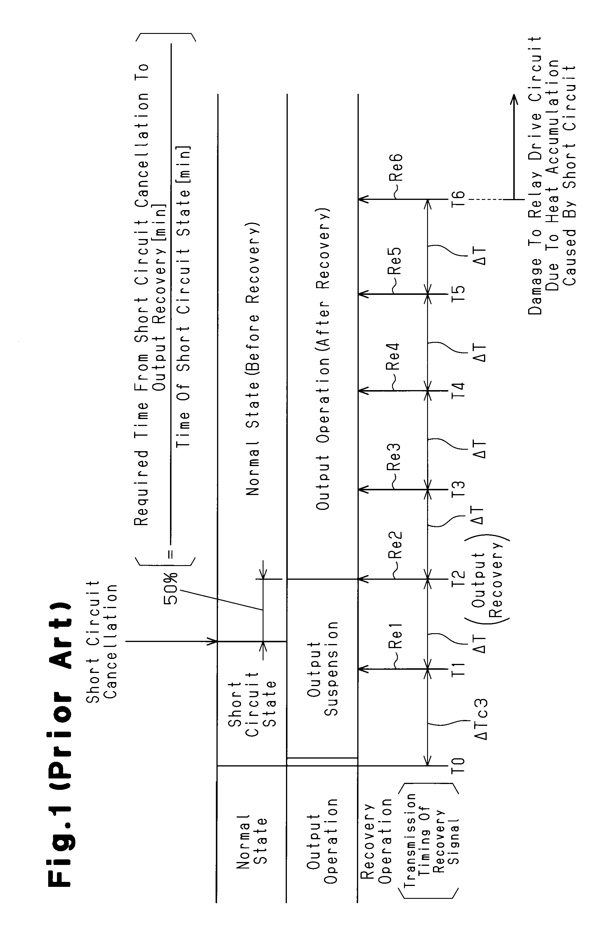
[0014]Still a further aspect of the present invention provides a method for protecting a relay drive circuit from damage caused by a short circuit, in which the relay drive circuit outputs a drive current to a load. The method includes detecting the occurrence of the short circuit between the load and the relay drive circuit, suspending an output operation of the relay drive circuit when the short circuit occurs, and intermittently transmitting a recovery signal to the relay drive circuit in a certain time interval after a predetermined time elapses from when the short circuit occurs to recover the output operation of the relay drive circuit. The intermittently transmitting a recovery signal includes gradually increasing the time interval whenever the recovery signal is transmitted so that when D1 represents the time during which the short circuit is occurring and D2 represents the time from when the short circuit is cancelled to when the output operation of the relay drive circuit is recovered, a time ratio expressed by D2 / D1 becomes less than or equal to a predetermined value.

Problems solved by technology

When a short circuit occurs at the output side of the relay drive circuit, excessive short circuit current may flow to the relay drive circuit.
This may damage the relay drive circuit.
As a result, heat generated by the short circuit current is accumulated as time elapses.
This may damage the relay drive circuit (transistors etc.).
However, the time ratio is 50% and relatively long.
Such a result is not satisfactory.
However, this would be inconvenient to the user.

Method used


Image

  • Short circuit protection circuit
  • Short circuit protection circuit
  • Short circuit protection circuit

Examples


first embodiment

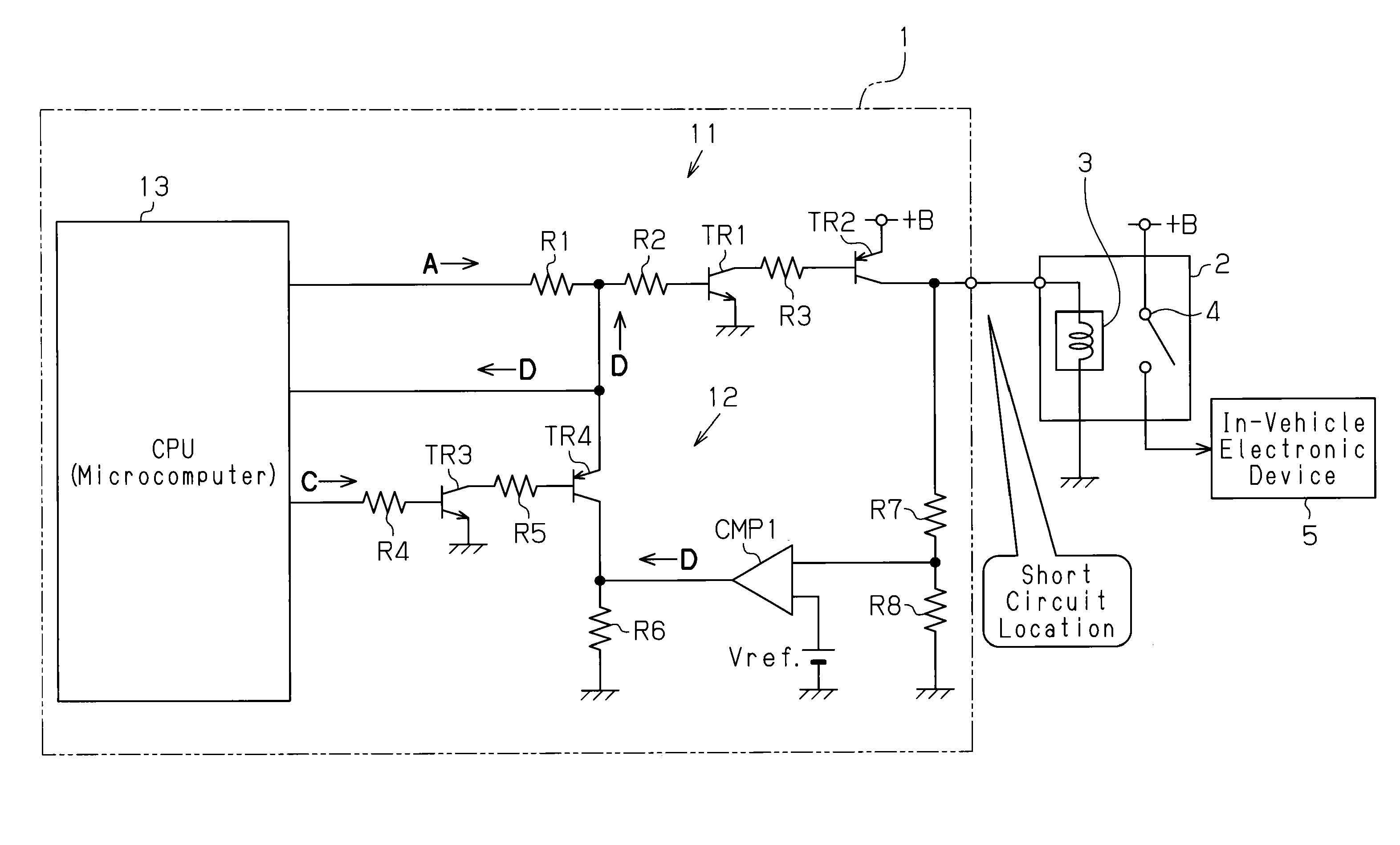
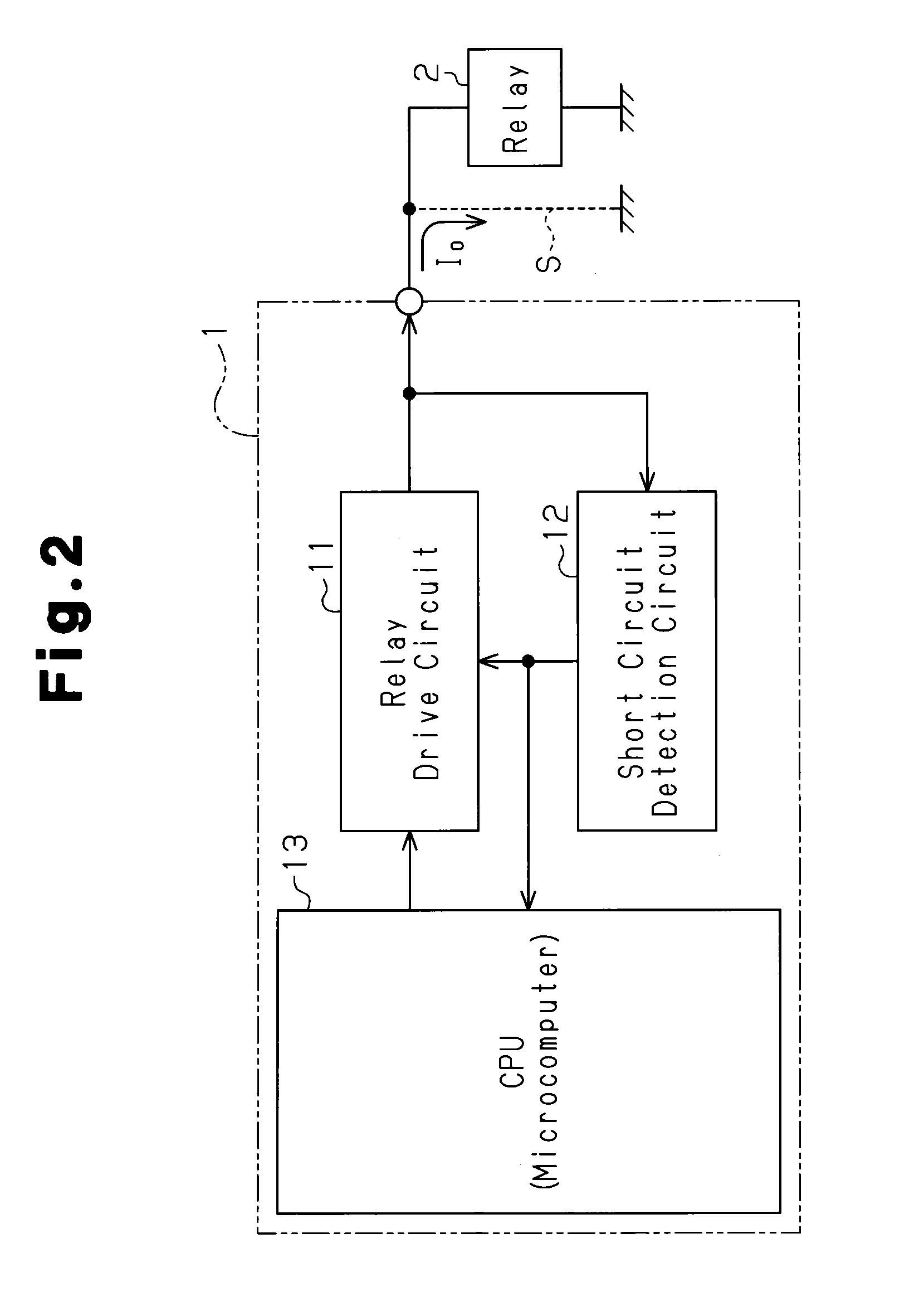
[0026]Referring to FIG. 2, in the first embodiment, an electronic control unit (ECU) 1 (controller), which functions as a short circuit protection circuit, is arranged in an in-vehicle electronic device, which is installed in a vehicle. The ECU 1 includes a relay drive circuit 11, a short circuit detection circuit 12, and a central processing unit (CPU) 13 (microcomputer). The relay drive circuit 11 outputs drive current, which flows to a relay 2, in response to a relay drive signal A, which serves as a first control signal. The short circuit detection circuit 12 detects a short circuit S (short circuit current I0) at the output side of the relay drive circuit 11. The CPU 13 is connected to the relay drive circuit 11 and the short circuit detection circuit 12 to control the circuits 11 and 12.

[0027]Referring to FIG. 3, the relay drive circuit 11 includes an npn transistor TR1, which has a base terminal connected to the CPU 13 via series-connected resistors R1 and R2, an emitter term...

second embodiment

[0052]Referring to FIG. 6, in the second embodiment, an ECU la (controller) functioning as a short circuit protection circuit is arranged in an in-vehicle electronic device installed in a vehicle. The ECU la includes two relay drive circuits 11a and 11b, two short circuit detection circuits 12a and 12b, and a CPU 113. The relay drive circuits 11a and 11b each output drive current to a relay 2 based on an input relay drive signal A (control signal). The short circuit detection circuits 12a and 12b detect the occurrence of a short circuit S (short circuit current I0) at the output sides of the relay drive circuits 11a and 11b, respectively. The CPU 113, which functions as a controller, is connected to the relay drive circuits 11a and 11b and the short circuit detection circuits 12a and 12b to control the circuits 11a, 12a, 11a, and 11b. In this manner, the ECU 1a includes a plurality of (two in FIG. 6) short circuit protection units, with each unit including the relay drive circuit 11...


PUM


Abstract

A short circuit protection circuit which readily recovers a relay drive circuit to an output operation state after a short circuit is cancelled while preventing the relay drive circuit from being damaged by a short circuit. The relay drive circuit outputs a drive current to a load in accordance with a first control signal. A short circuit detection circuit detects the occurrence of a short circuit at an output side of the relay drive circuit and suspends output operation of the relay drive circuit when a short circuit occurs. Further, the short circuit detection circuit intermittently transmits a recovery signal to the relay drive circuit in a certain time interval after a predetermined time elapses from when the short circuit occurs to recover the output operation of the relay drive circuit. The time interval is gradually increased whenever the recovery signal is transmitted.

Description

CROSS-REFERENCE TO RELATED APPLICATIONS[0001]This application is based upon and claims the benefit of priority from the prior Japanese Patent Application No. 2008-101630, filed on Apr. 9, 2008, the entire contents of which are incorporated herein by reference.BACKGROUND OF THE INVENTION[0002]The present invention relates to a short circuit protection circuit for a relay arranged in an electronic device that is installed in a vehicle.[0003]A relay drive circuit for an in-vehicle electronic device installed in a vehicle supplies a relay (load) with drive current based on an input control signal. When a short circuit occurs at the output side of the relay drive circuit, excessive short circuit current may flow to the relay drive circuit. This may damage the relay drive circuit.[0004]Japanese Laid-Open Patent Publication No. 2001-25150 describes a short circuit protection circuit including a large current fuse located between a power supply and a relay drive circuit. The fuse melts and ...

Claims


Application Information

Patent Timeline
Patent Type & Authority Patents(United States)
IPC IPC(8): H02H3/00H02H5/00H02H3/06
CPCH01H47/002H01H47/32
Inventor IMAI, TAKAOMORI, HIROSHIITO, JUNNIWA, HISAO
Owner KK TOKAI RIKA DENKI SEISAKUSHO
Learn More