
Imaging apparatus

a technology of imaging apparatus and image, which is applied in the field of imaging apparatus, can solve the problems of increasing the amount of computation, not disclosing the method of calculating the distortion, and increasing the distortion of an image detected by the imaging device of a camera using a fisheye lens or a wide-angle lens, so as to reduce the other portions, correct the distortion of the captured image, and expand the portion of the captured image

Active Publication Date: 2012-03-13
ALPS ALPINE CO LTD
View PDF12 Cites 8 Cited by
  • Summary
  • Abstract
  • Description
  • Claims
  • Application Information

AI Technical Summary

Benefits of technology

This approach effectively corrects image distortion while maintaining a wide-angle display, reducing computational load and improving compatibility by dynamically adjusting the enlargement ratio, resulting in a high-visibility, distortion-reduced image display.

Problems solved by technology

However, the distortion of an image detected by an imaging device of a camera using a fisheye lens or a wide-angle lens is increased as a field angle from the optical axis of the lens is increased.
However, JP-A-2000-324386 does not disclose a method of calculating the distortion.
Since the image captured by the camera using the fisheye lens or the wide-angle lens has a three-dimensional depth, a three-dimensional geometric process is needed to calculate the distortion of the image, which results in an increase in the amount of computation.
In addition, a large load is applied to a CPU in order to continuously calculate the distortion of the image captured by the camera using the fisheye lens or the wide-angle lens.
That is, since the conversion table corresponds to a predetermined region of the image captured by the camera, the conversion table has low compatibility.
For example, when the angle at which the camera is attached deviates from the original position and the actual image is different from the image of a predetermined section in the conversion table, it is difficult to exactly correct the captured image.

Method used


Image

  • Imaging apparatus
  • Imaging apparatus
  • Imaging apparatus

Examples


Embodiment Construction

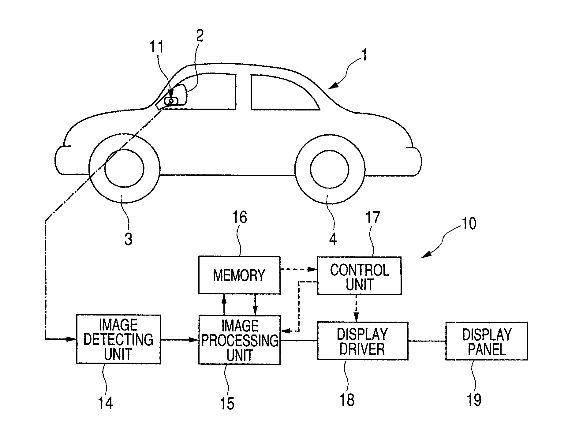
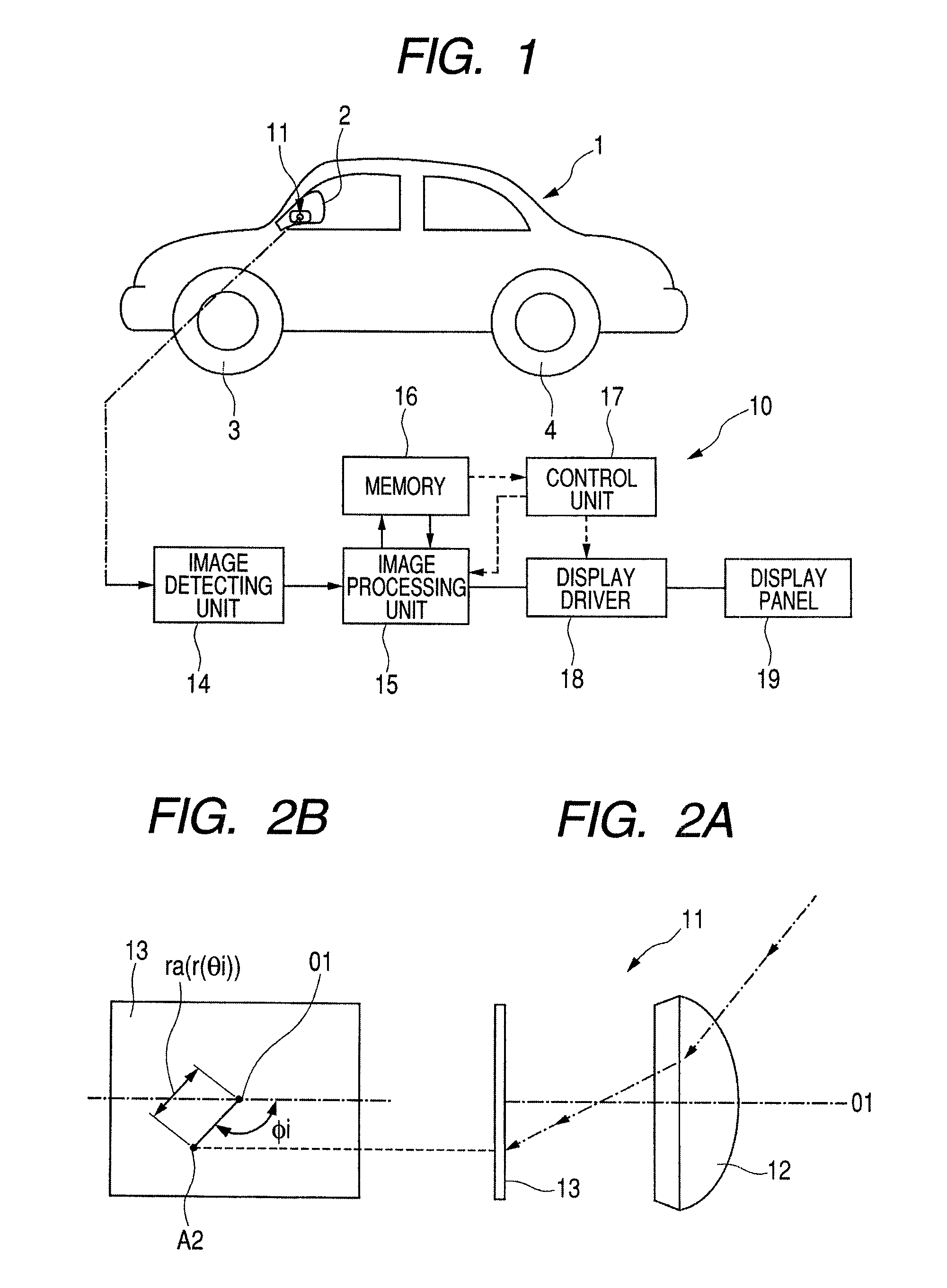
[0028]FIG. 1 is a block diagram illustrating an imaging apparatus according to an embodiment of the invention.

[0029]An imaging apparatus 10 includes a fisheye camera 11. For example, the fisheye camera 11 is attached to the body of a vehicle 1. In the embodiment shown in FIG. 1, the fisheye camera 11 is mounted to a fender mirror 2 of the vehicle 1, and the optical axis of the fisheye camera is positioned between a front wheel 3 and a rear wheel 4. The optical axis is aligned in the vertical direction of the plane of FIG. 1 and is inclined downward at an angel of about 45° with respect to the other surface.

[0030]As shown in FIG. 2A, the fisheye camera 11 includes a fisheye lens 12 and an imaging device 13 having a plurality of detection points that detect light focused by the fisheye lens 12. The imaging device 13 is, for example, a CCD or a CMOS.

[0031]Image signals (brightness signals) detected at the detection points of the imaging device 13 are converted into digital image signal...


PUM


Abstract

Disclosed is an imaging apparatus capable of enlarging a portion of an image captured by an imaging device of a fisheye camera and displaying the enlarged image on a display screen with little distortion. The imaging apparatus enlarges a section, which is a portion of an image captured by a fisheye camera, and displays the section on a display screen such that the enlargement ratios of points in the section are different from each other. An image processing method uses a change function that changes the enlargement ratio of a field angle depending on the place is used, and converts a portion of the captured image into a central projection image to generate a display image. The use of the change function makes it possible to generate a display image having high visibility.

Description

CLAIM OF PRIORITY[0001]This application claims benefit of the Japanese Patent Application No. 2007-298854 filed on Nov. 19, 2007, the entire content of which is hereby incorporated by reference.BACKGROUND[0002]1. Technical Field[0003]The present invention relates to an imaging apparatus that uses an imaging device to detect light focused by various types of lenses, such as a fisheye lens and a wide-angle lens, enlarges some of image signals detected by the imaging device, corrects distortion, and displays an image on a display screen.[0004]2. Related Art[0005]An imaging apparatus that uses a camera including a fisheye lens or an optical lens and an imaging device to capture an external image and displays the image on a display device has been used for security or vehicles. In particular, in an imaging apparatus for a vehicle, a camera is attached to the body of the vehicle and captures an external image in the wide range. However, the distortion of an image detected by an imaging de...

Claims


Application Information

Patent Timeline
Patent Type & Authority Patents(United States)
IPC IPC(8): H04N5/228H04N9/47H04N7/18H04N23/40H04N23/75
CPCB60R1/00G06T3/0018H04N5/23238H04N5/2628B60R2300/108B60R2300/30B60R2300/306H04N23/698G06T3/047B60R1/26B60R1/28
Inventor YAMASHITA, TATSUMAROKAMATA, TOMOYA
Owner ALPS ALPINE CO LTD
Learn More