Localized corrosion monitoring device for limited conductivity fluids

a technology of conductivity fluid and monitoring device, which is applied in the direction of liquid/fluent solid measurement, material electrochemical variables, instruments, etc., can solve the problems of loss of production, localized corrosion of equipment, and corrosion failure in many oil and gas production systems, so as to remove the effect of temperature swing and accurately measure the temperatur

Active Publication Date: 2012-03-13
BAKER HUGHES HLDG LLC
View PDF5 Cites 4 Cited by
  • Summary
  • Abstract
  • Description
  • Claims
  • Application Information

AI Technical Summary

Benefits of technology

[0018]R1 and R2 are the resistance measurements over time period Δt.The potential of the metal strip V is measured relative to the reference electrode. Performing these two measurements, that is, measuring the resistance across the length of the test electrode over a period of time Δt and measuring the potential of metal strip V, may be performed independently at a frequency chosen by the operator without need to cease either of the measurements. In LPR, one would have to stop measurements, but this is not necessary with the method herein. An advantage over previous methods such as LPR is that continuous measurements of potential and resistance may be taken without interruption. This may be done by using a rolling or moving average or other suitable technique. Interruption and restarting measurements, as in prior methods, tends to be accompanied by inaccuracy immediately after the interruption, which is avoided in this method. Determining Rp in this way produces more meaningful values of current transients.

Problems solved by technology

Localized corrosion of equipment is a serious problem in many industries and processes.
In particular, corrosion failures in many oil and gas production systems, oil / gas / water transmission pipelines, petrochemical and chemical processing plants, fossil fuel and nuclear power plants involve localized corrosion.
Localized corrosion may result in loss of production, increase in maintenance costs, environmental pollution and potential health and safety hazards, etc.
While pitting is a type of localized corrosion, the locally corrosive pits may eventually cover substantial portions of a corroded electrically conductive article's surface.
Localized corrosion may occur when small local sites are attacked at a much higher rate than the rest of the surface.
Localized corrosion occurs when corrosion works with other destructive forces such as stress, fatigue, erosion and chemical attacks.
Localized corrosion may cause more damage than any of these destructive forces individually.
Localized corrosion is highly stochastic in nature and its occurrence is fairly unpredictable.
Although the above techniques are widely employed, they (1) possess limitations in that they only provide information on uniform (general) corrosion conditions because they provide an average signal for the surface of the electrode being monitored; and (2) depending upon the environment, metallic material, and corrosion type, the assumption that the corrosion rate is inversely proportional to the measured charge transfer or polarization resistance is invalid because the corrosion is of a localized nature.
Disadvantages of this system, however, include the fact that the working electrodes need to be identical to obtain accurate readings and obtaining such identical electrodes is difficult, if not impossible.
Another problem is that it is unknown which electrode is responding to reveal the corrosion, due to the fact that this system requires the use of two working electrodes which limits where such systems can be employed.
Furthermore, distinguishing between various types of localized corrosion is, at minimal, difficult due to the fact that both electrodes contribute to the system response.

Method used


Image

  • Localized corrosion monitoring device for limited conductivity fluids
  • Localized corrosion monitoring device for limited conductivity fluids
  • Localized corrosion monitoring device for limited conductivity fluids

Examples


Embodiment Construction

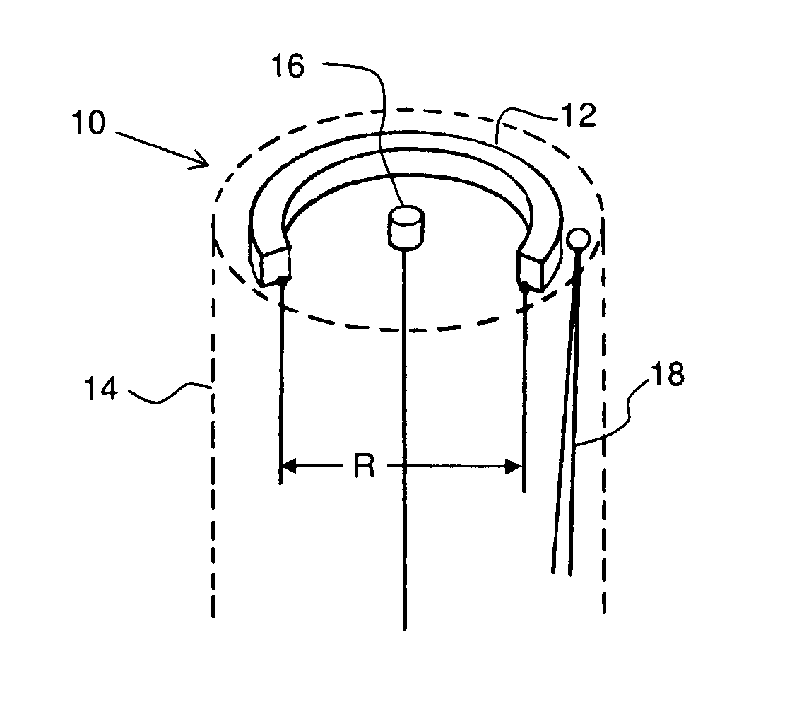
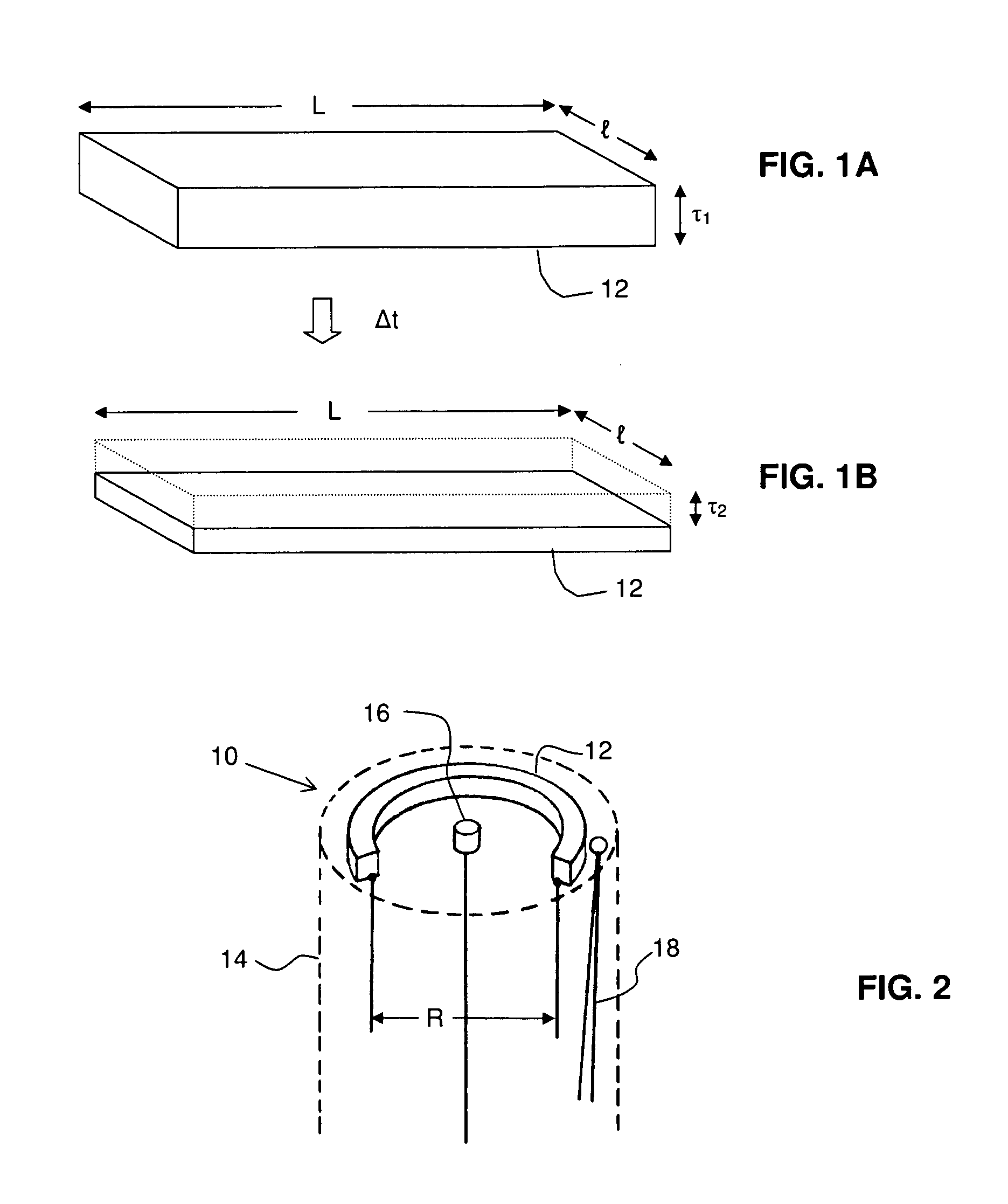
[0028]Methods and apparatus for the detection and characterization of the corrosion behavior in systems where localized corrosion occurs (in one non-limiting embodiment, in the form of pitting) and is quantitatively evaluated are described. The severity, frequency and time / space distribution of the localized events may be determined from potential and current measurements recorded from the corroding systems.

[0029]More specifically, in one non-limiting embodiment, localized corrosion has been determined semi-quantitatively previously by measuring the galvanic current between two electrodes and monitoring the potential of the couple using a third reference electrode. This is typically known as current / voltage (electrochemical) noise (ECN). The technique correlates the two signals using a range of mathematical methods to calculate the general corrosion rate (Rp=ΔV / ΔI) and estimate the likelihood of localized corrosion (LI=σi / irms), where LI refers to Localization Index, σi refers to th...


PUM

PropertyMeasurementUnit
Densityaaaaaaaaaa
physical thicknessesaaaaaaaaaa
thicknessesaaaaaaaaaa

Abstract

A localized corrosion monitoring (LCM) device is modified to obtain polarization resistance (Rp) from electrical resistance of a probe having a strip of metal under investigation (test electrode), a reference electrode and a temperature sensor (e.g. thermocouple). This configuration allows the probe to be used in areas where only a thin film of conductive fluid is available or required to provide potential monitoring. Thus, the applicability of the LCM technique is broadened. All the above devices are expected to be configured in one item of equipment, except for the probe which may be remotely located from the rest of the equipment.

Description

CROSS-REFERENCE TO RELATED APPLICATION[0001]This application claims the benefit of U.S. Provisional Patent Application No. 61 / 022,944 filed Jan. 23, 2008.TECHNICAL FIELD[0002]The present invention relates to electrochemical methods and systems for measuring corrosion rate, particularly to methods and apparatus for evaluating localized corrosion, and most particularly relates in a non-limiting embodiment, to methods and apparatus for measuring localized corrosion in hydrocarbon pipelines, transportation systems, processing vessels and fluid handling equipment by obtaining polarization resistance (Rp).DESCRIPTION OF THE RELATED ART[0003]Localized corrosion of equipment is a serious problem in many industries and processes. In particular, corrosion failures in many oil and gas production systems, oil / gas / water transmission pipelines, petrochemical and chemical processing plants, fossil fuel and nuclear power plants involve localized corrosion. Localized corrosion may result in loss of ...

Claims


Application Information

Patent Timeline
Patent Type & Authority Patents(United States)
IPC IPC(8): G01F1/64
CPCG01N17/04G01N27/20G01N27/26
Inventor HAMMONDS, PAULJOVANCICEVIC, VLADIMIR
Owner BAKER HUGHES HLDG LLC
Why Eureka
Try Eureka