
Method and apparatus for setting a feedback power of a fundamental frequency clocked converter

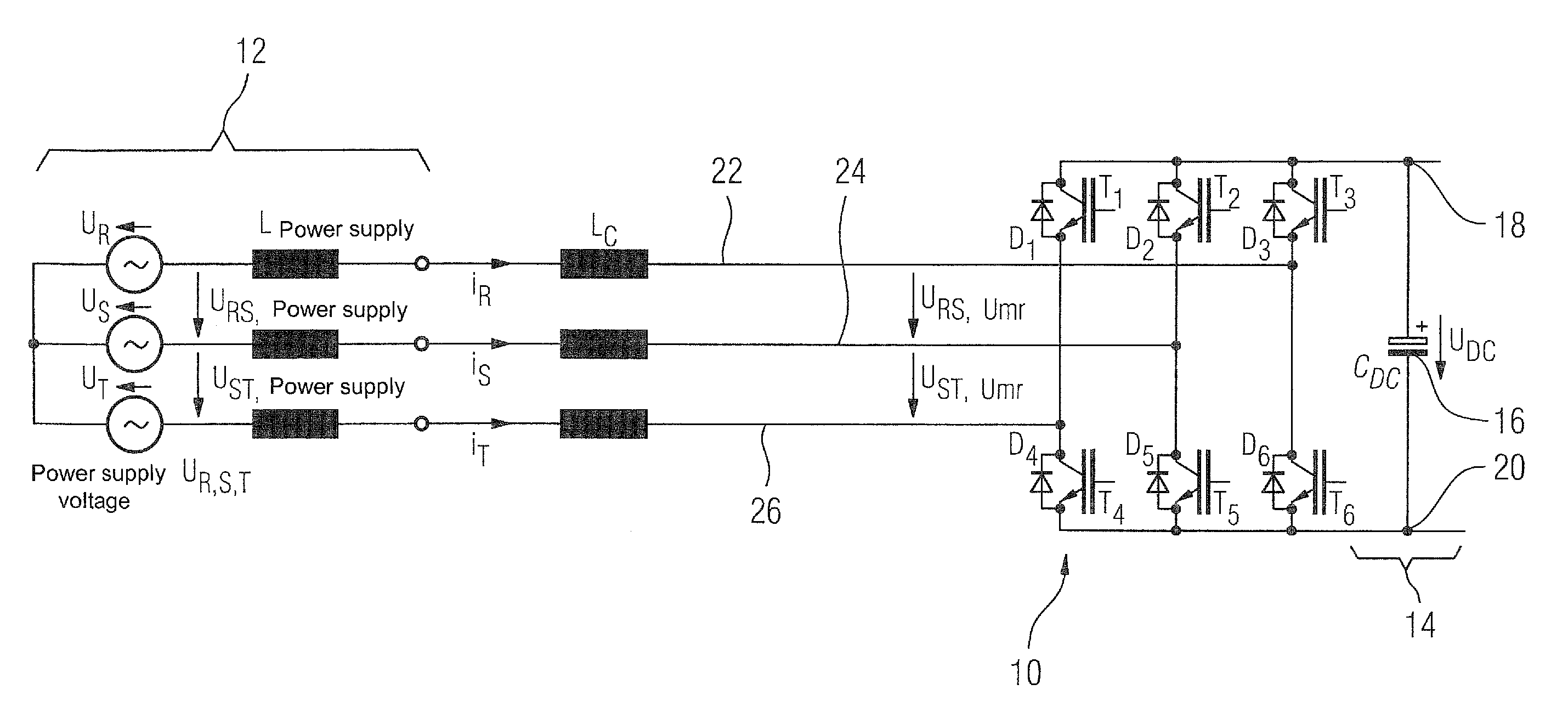
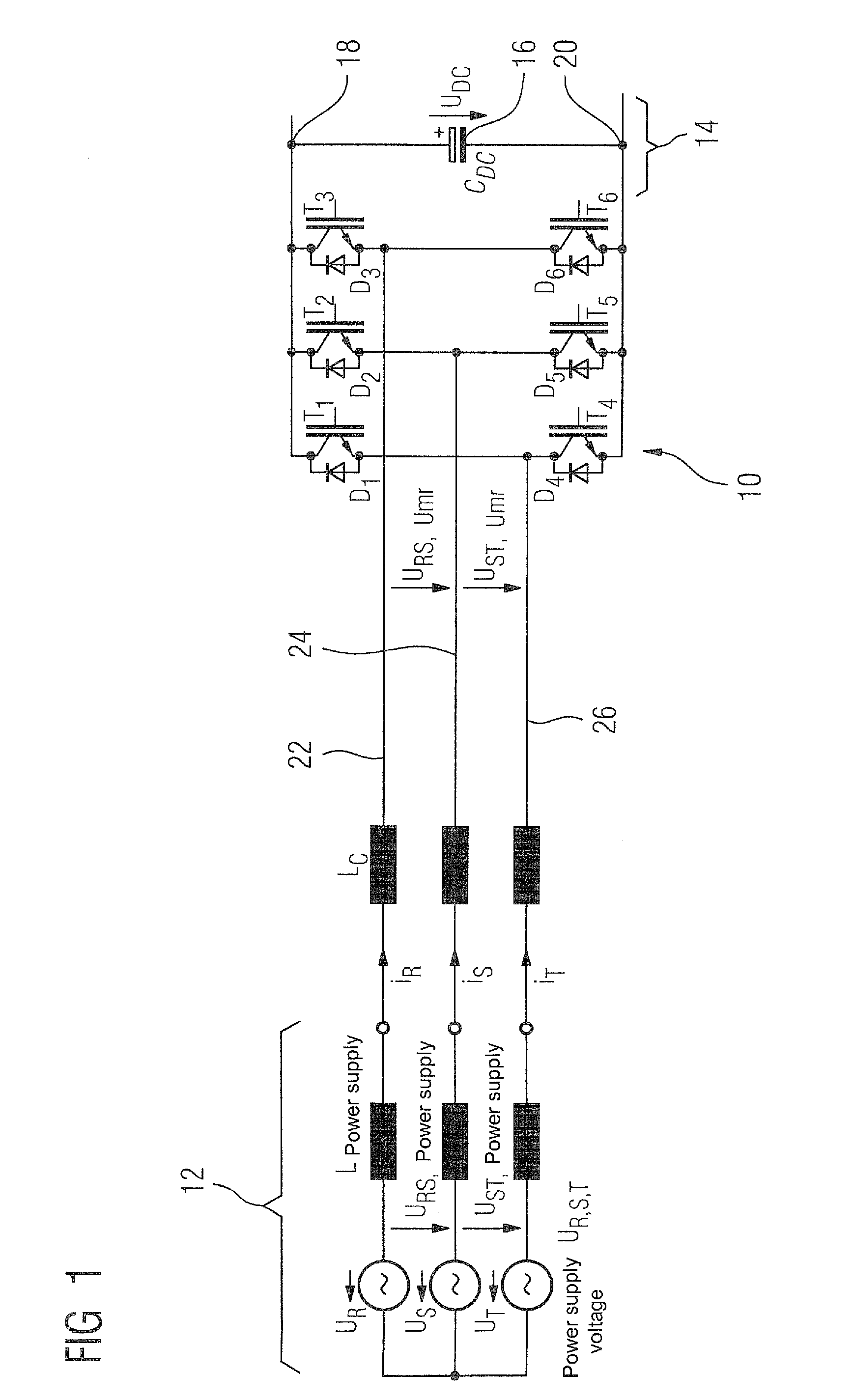
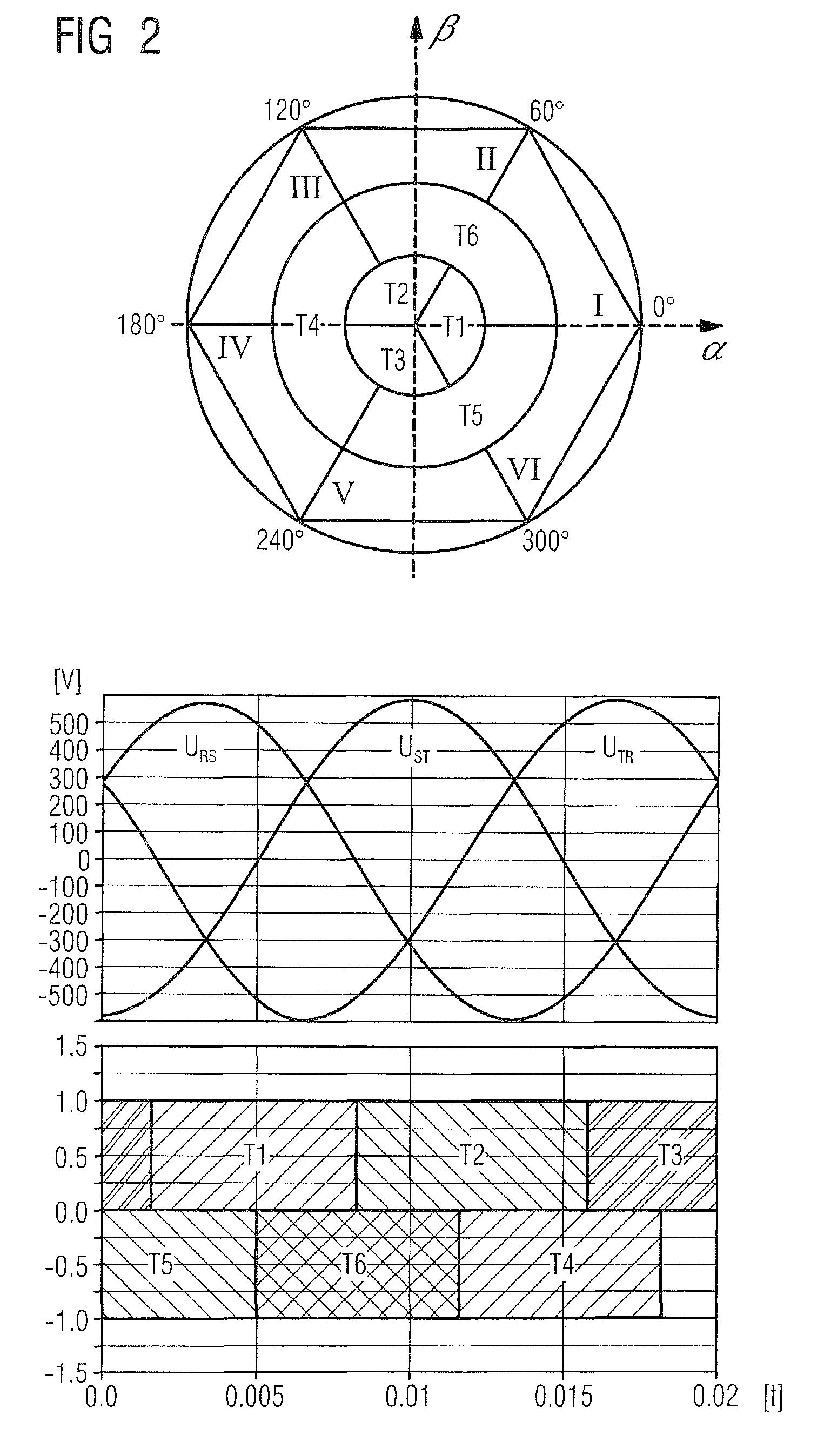
a fundamental frequency clocked converter and feedback power technology, applied in the direction of electric variable regulation, process and machine control, instruments, etc., can solve the problems of low switching loss, large reactive power requirement, and loading of the power supply system for the user, so as to avoid rapid and large changes in the dc link voltage and reduce switching losses

Active Publication Date: 2012-03-06
SIEMENS AG
View PDF8 Cites 7 Cited by
  • Summary
  • Abstract
  • Description
  • Claims
  • Application Information

AI Technical Summary

Benefits of technology

[0016]According to another embodiment, the characteristic curve may be supplemented by an integrating term, which successively reduces the switch-on delay. In addition, the switch-on delay may also define a negative switch-off delay.
[0017]With the invention, voltage-dependent feedback can be enabled easily and robustly in fundamental frequency operation. By preventing an abrupt enablement of the feedback, a sudden decrease in the DC link voltage and a very rapid increase in the power supply current are eliminated, with the following advantages:
[0019]A threshold value for the DC link voltage for enabling the feedback can be high (large current-driving differential voltage in the case of enabling the feedback). The energy buffering of the DC link in the case of load changes can thus be better utilized. This results, in particular, in improved efficiency, possible continued operation in the event of power supply disturbances, and improved thermal loading.
[0020]If required, the DC link voltage can be increased / controlled for particular applications (e.g. the operating characteristic of a so-called chopper can be realized at lower costs).
[0022]On average reduced thermal loading of the converter and of the additional components.

Problems solved by technology

Since the semiconductor switches, which can also be referred to as current valves, are not clocked at high frequency, this results for example in low switching losses and furthermore in the possibility of using simple and cost-effective commutation inductors and power supply filters, and finally in low excitation of system oscillations that can lead e.g. to high motor bearing currents.
A considerable disadvantage of this operating mode hitherto has been, for example, that a relatively large reactive power requirement arises in the case of no load or in the case of weak loading of the converter.
This leads to a loading of the power supply system for the user and to increased energy costs.
The technology thereby becomes more difficult to impart or market.
A further disadvantage is that, in the case of power supply voltage dips, the DC link voltage follows the power supply voltage and energy stored in the DC link for buffering is thus lost.
Moreover, the power supply voltage and thus the natural rectification voltage may be subject to large fluctuations, for which the thresholds must likewise be sufficiently spaced apart.
During operation, however, a rapid change in the DC link voltage can have adverse effects on the process to be operated / the application to be operated and lead e.g. to a reduction of the torque accuracy in the case of electric drives and hence deviations from a desired position.
To date, the problem outlined above has been solved e.g. either by using a large commutation inductance with the disadvantages of increased costs and an undesirable increased voltage drop, or by using a large DC link capacitance with the disadvantages of increased costs, or by means of a control-technological compensation of the voltage changes in the DC link and likewise the disadvantages of increased costs owing to requirements made of a short controller clock cycle or on account of additionally required circuitry measures.
In one conventional converter, a changeover is made between fundamental frequency uncontrolled operation and clocked voltage-controlled operation when the operating mode of the converter at a point in time is found to be unsuitable for the instantaneous power requirements made of the converter.

Method used


Image

  • Method and apparatus for setting a feedback power of a fundamental frequency clocked converter
  • Method and apparatus for setting a feedback power of a fundamental frequency clocked converter
  • Method and apparatus for setting a feedback power of a fundamental frequency clocked converter

Examples


Embodiment Construction

[0038]Throughout all the figures, same or corresponding elements may generally be indicated by same reference numerals. These depicted embodiments are to be understood as illustrative of the invention and not as limiting in any way. Rather, numerous alterations and modifications are possible in the context of the present disclosure, in particular those variants, elements and combinations which, for example through combination or modification of individual features or elements or method steps in conjunction with the features or elements or method steps which are described in the general or specific part of the description and are contained in the claims and / or the drawing, can be inferred by the person skilled in the art with regard to achieving the object and, through combinable features, lead to a new subject matter or to new method steps or method step sequences. It should also be understood that the figures are not necessarily to scale and that the embodiments are sometimes illus...


PUM


Abstract

A method and an apparatus for setting a feedback power of a converter clocked at a fundamental frequency on the power supply side are disclosed. The converter includes a bridge circuit equipped with controllable semiconductor switches, wherein the semiconductor switches are clocked at the fundamental frequency depending on a desired direction of a power flow through the bridge circuit. Drive signals for the semiconductor switches are derived from the clock pulses at the fundamental frequency and a switch-on delay which depends on a DC link voltage of a DC link connected to the converter. The switch-on delay is determined based on a predetermined characteristic curve that depends on the DC link voltage.

Description

CROSS-REFERENCES TO RELATED APPLICATIONS[0001]This application claims the priority of European Patent Application, Serial No. EP08012432, filed Jul. 9, 2008, pursuant to 35 U.S.C. 119(a)-(d), the content of which is incorporated herein by reference in its entirety as if fully set forth herein.BACKGROUND OF THE INVENTION[0002]The present invention relates to a method for setting, in particular for variably setting, a feedback power of a fundamental frequency clocked converter on the power supply side with a bridge circuit equipped with controllable semiconductor switches, and to an apparatus provided for implementing the method.[0003]The following discussion of related art is provided to assist the reader in understanding the advantages of the invention, and is not to be construed as an admission that this related art is prior art to this invention.[0004]A converter device or a converter circuit can include at least one power supply connection and phase sections which are provided th...

Claims


Application Information

Patent Timeline
Patent Type & Authority Patents(United States)
IPC IPC(8): H02M7/219
CPCH02J3/1892H02M7/797
Inventor BENESCH, NORBERT
Owner SIEMENS AG
Learn More