
Group signature scheme

Active Publication Date: 2012-02-28
NEC CORP
View PDF3 Cites 11 Cited by
  • Summary
  • Abstract
  • Description
  • Claims
  • Application Information

AI Technical Summary

Benefits of technology

[0020]Therefore, an object of the present invention is to provide a group signature scheme where an open means is provided to not an issuer but an opener and a data required for operating the open means does not include a key pair of the issuer, so that it is possible to accurately operate the open means although the issuer generates the public key in an illegal manner.
[0041]According to one feature of the present invention, an open unit is provided to not an issuer but an opener, and a data required for operating the open unit does not include a key pair of the issuer, so that it is possible to accurately operate the open unit although the issuer generates the public key in an illegal manner.
[0044]In addition, according to another feature of the present invention, it is possible to prove the safety under only a strong RSA assumption, an L decision Diffie Helman assumption, and an random oracle assumption. In addition, since a discrete logarithm problem on a finite field with a prime factor of n as a modulus does not need to be difficult unlike Non-Patent Document 1, so that it is possible to reduce the number of bits of n down to a half of that of the scheme disclosed in Non-Patent Document 1.

Problems solved by technology

The schemes disclosed in Non-Patent Documents 1, 2, 6, and 7 have a problem in safety proof.
In addition, in the scheme disclosed in Non-Patent Documents 1 and 6, a manager may know a secret key of a user by generating a manager's own public key in an illegal manner.
In addition, although the manger is obligated to output a validity proof text of the public key, a safety thereof cannot be proven.
In addition, in a scheme where the manager is obligated to output the validity proof text of the public key and each user verifies the proof text, an efficiency thereof is deteriorated.

Method used


Image

  • Group signature scheme
  • Group signature scheme
  • Group signature scheme

Examples


first exemplary embodiment

[First Exemplary Embodiment]

[0084]In the embodiment, N, Z, Zn, and QZ(n) denote a set of all natural numbers, a ring of integers, a ring of integers of 0 to n-1, and a multiplicative group of quadratic residues in the Zn, respectively. A hash function of a set X is denoted by H_X. The number of bits of |n| of an integer n is denoted by ||n||. A prime number p of which (p-1) / 2 is a prime number is defined as a safe prime. An integer n which is a product of two safe primes having the same bit length is defined as a rigid integer (rigid modulus). A set of real numbers which are equal to or larger than a and less than b is denoted by [a, b).

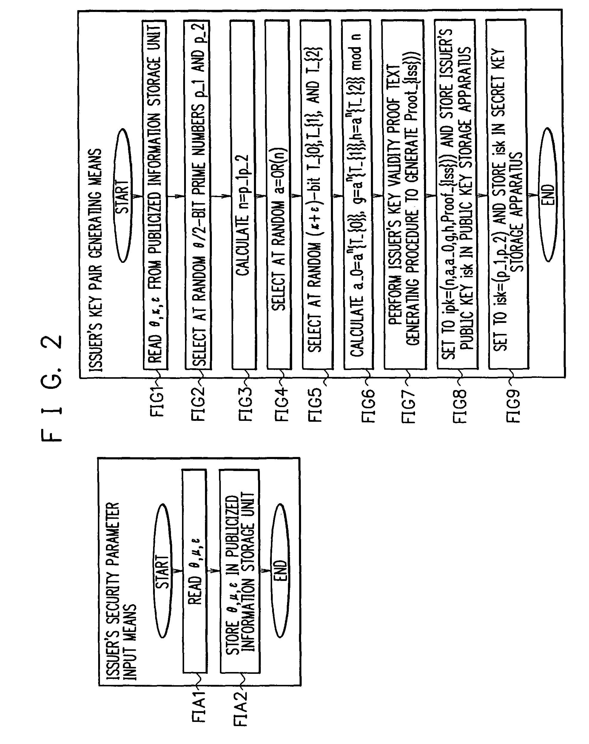
[0085]Security parameters are denoted by θ, κ, μ, and ε. In addition, λ=θ+κ+ε, γ=λ+μ+ε+8, Λ=[0, 2^λ]∩N, and Γ=(2^γ, 2^γ+2^λ) are satisfied.

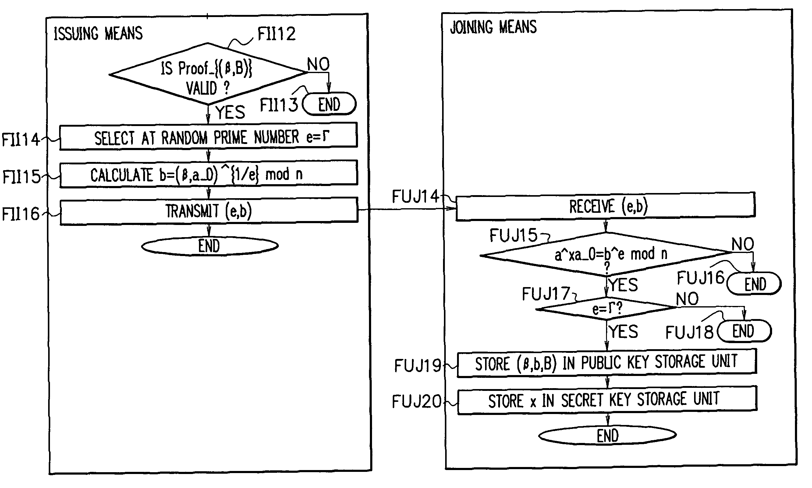
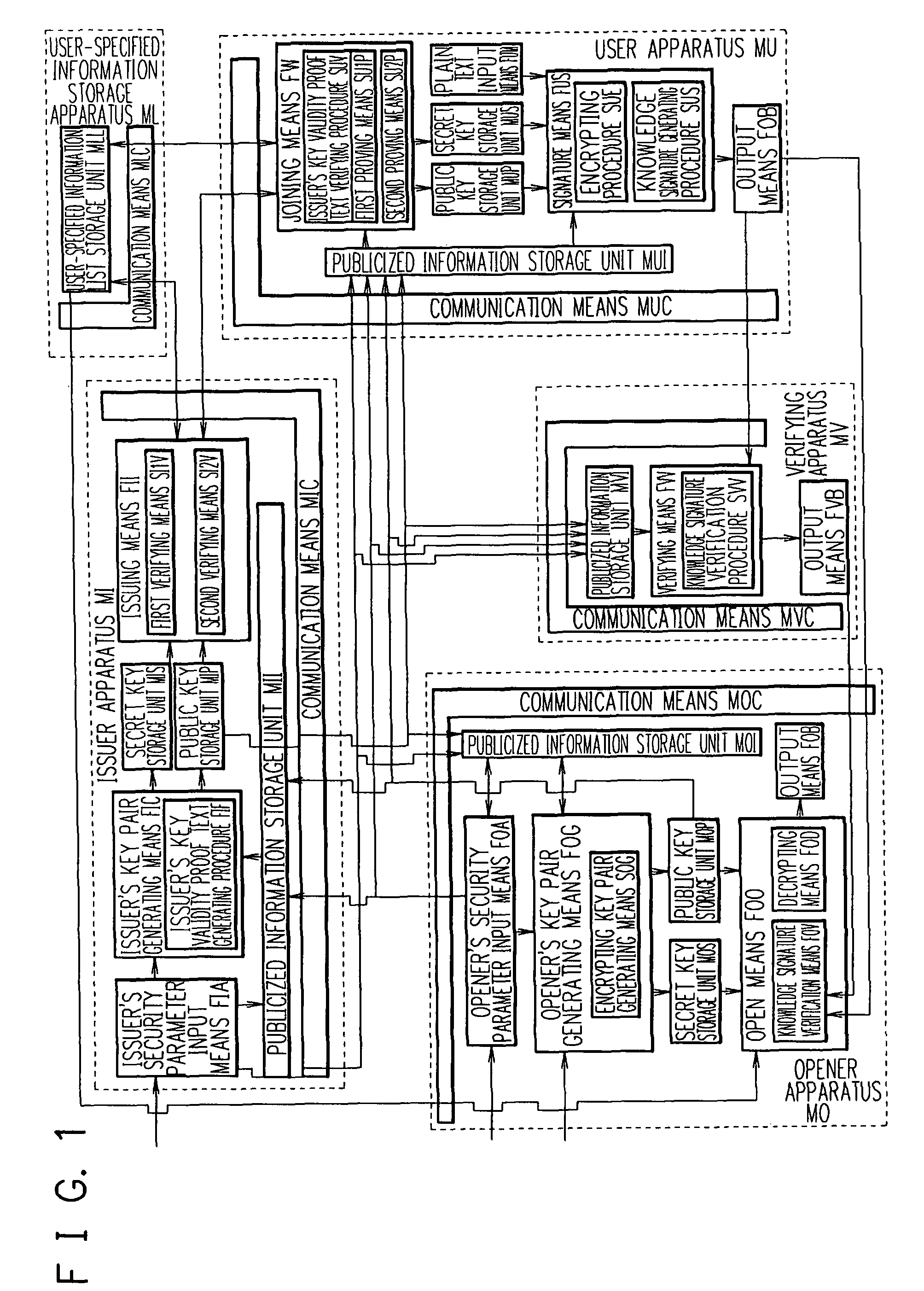
[0086]A construction of an apparatus according to the embodiment is described with reference to FIG. 1.

[0087]The apparatus according to the embodiment includes an issuer apparatus MI, a user-specified information ...

second exemplary embodiment

[Second Exemplary Embodiment]

[0179]A construction of an apparatus according to the embodiment is the same as that of the first exemplary embodiment except for the signature unit FUS and the verifying unit FVV.

[0180]Similarly to the signature unit FUS according to the first exemplary embodiment, the signature unit FUS generates Commit, 1, and Response. Next, (Commit, Response) is set to the signature text.

[0181]Processes of the verifying unit FVV are described with reference to FIG. 16. When (M, Signature) is input, the verifying apparatus MV reads (θ, μ, ε, κ, issuer's public key ipk, opener public key opk) (SVV1). Here, Signature=(Cipher, Commit, Response), Cipher=(G′, H′—1, H′—2), Commit=(χ_b, (χ_e, χ_u), d—1, d—2, (d_e, d_u), (U, V—1, V—2)), and Response=(x″, e″, u″, s″, t″, u″_e, t″_e, ρ″) .

[0182]Firstly, the verifying unit FVV calculates 1=Hash_{μ-bit integer}(issuer's public key ipk, opener public key opk, Cipher, Commit, M) by using Commit which is a portion of the signature ...

third exemplary embodiment

[Third Exemplary Embodiment]

[0183]In the embodiment, an Identity Escrow scheme is implemented. The Identity Escrow scheme is disclosed in Non-Patent Document 12.

[0184]A construction of an apparatus according to the embodiment is similar to that of the first exemplary embodiment (see FIG. 17). However, the signature unit FUS is replaced with a to-be-authenticated unit FUA, and the signature generating procedure SUS is replaced with a proving procedure SUP. In addition, the verifying unit SUV according to the first exemplary embodiment is different from the verifying unit SUV according to third exemplary embodiment. The to-be-authenticated unit FUA and the verifying unit SUV communicate with each other to perform calculations. Unlike the first exemplary embodiment, the user apparatus MU does not include a unit FOB for outputting a signature.

[0185]Detailed processes of the to-be-authenticated unit FUA and the verifying unit SUV are described. Firstly, the user apparatus MU performs an ...


PUM


Abstract

An efficient and safe group signature scheme is provided. According to the present invention, an open unit is provided to not an issuer but an opener, and a data required for operating the open unit does not include a key pair of the issuer, so that it is possible to accurately operate the open unit even if the issuer generates the public key in an illegal manner. In addition, it is possible to prove that a key pair of a member cannot be counterfeited. It is possible to implement from a discrete logarithm assumption a feature that a cipher text, that is, a portion of a signature text can be decrypted only by the opener in a method which is the same as a method representing that an ElGamal crypto scheme is safe. In addition, it is possible to implement from a random oracle assumption a feature that a knowledge signature has an extractability in a method which is the same as a method proving that a Schnorr signature is safe.

Description

TECHNICAL FIELD[0001]The present invention relates to a group signature scheme and, more particularly, to an efficient and safe group signature scheme.BACKGROUND ART[0002]In a group signature scheme, only the user who is identified as a member of a group by a manager can generate a signature text anonymously as the member of the group, and only the manager can specify a signer.[0003]Recently, several group signature schemes have been proposed. As examples of the proposed group signature schemes, there are an RSA-based scheme (see Non-Patent Documents 1 and 6), a pairing-based scheme (see Non-Patent Documents 3, 4, and 7), and a Nyberg-Rueppel-based scheme (see Non-Patent Document 2).[0004]Non-Patent Document 1:G.Ateniese, J. Camenisch, M. joye, and G. Tsudik. A Practical and Provably Secure Coalition-Resistant Group Signature Scheme. In advances in Crytology—CRYPTO 2000, vol.1880 of LNCS, pp.255-270, Springer -Verlag, 2000.[0005]Non-Patent Document 2:Giuseppe Ateniese and Breno de M...

Claims


Application Information

Patent Timeline
IPC IPC(8): H04L9/32
CPCH04L9/3013H04L9/302H04L9/3255H04L2209/42G09C1/00
Inventor TERANISHI, ISAMU
Owner NEC CORP
Learn More