
Screen with capacitive touch zones

a capacitive touch and screen technology, applied in the direction of instruments, electric digital data processing, input/output process of data processing, etc., can solve the problems of interference with the visibility of information displayed, the electrodes are always at least partially visible, etc., to achieve the effect of improving optical compensation and high level of precision

Active Publication Date: 2012-02-28
EM MICROELECTRONIC-MARIN
View PDF11 Cites 11 Cited by
  • Summary
  • Abstract
  • Description
  • Claims
  • Application Information

AI Technical Summary

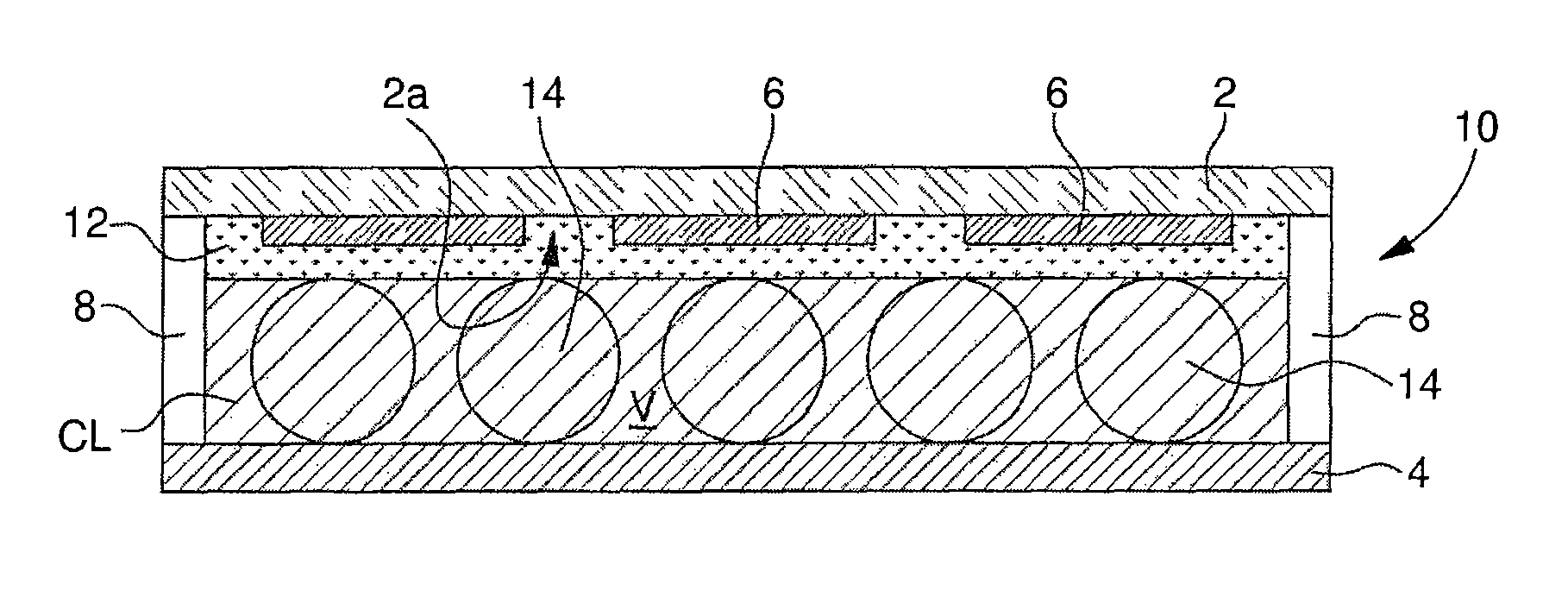
Benefits of technology

[0008]Owing to these features, the present invention provides a capacitive touch-zone screen including means that guarantee a constant parallelism between the first and second substrates. This prevents any risk of the electronic control circuit of the portable object associated with a touch screen according to the invention erroneously interpreting the variation measurement of the capacitance associated with a touch zone, for example because the user presses too hard on the screen and thus alters the distance between the two substrates.
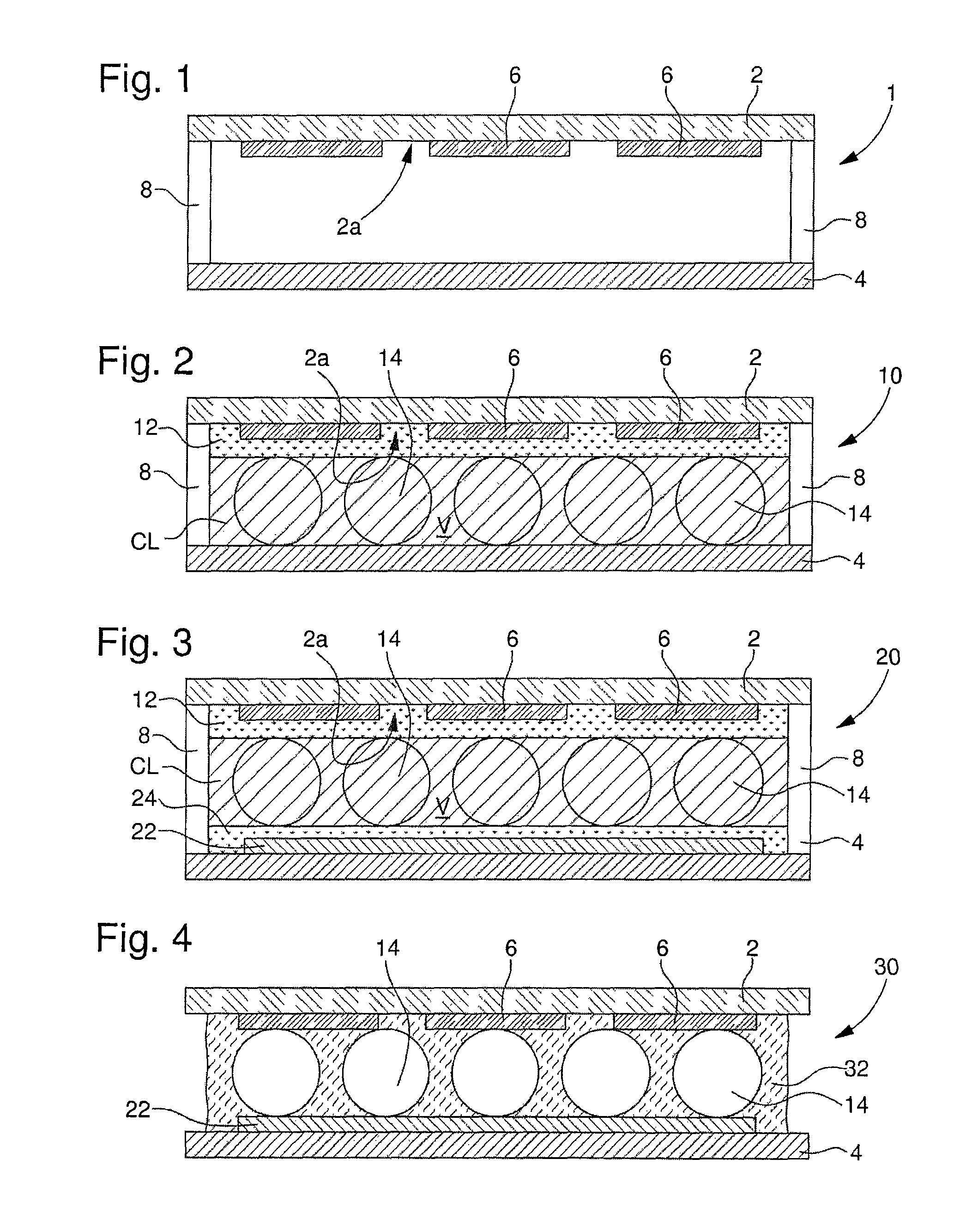
[0012]The sealing frame joins the first and second substrates in a solid and reliable manner. Moreover, the volume delimited by the sealing frame is advantageously filled with a transparent, anisotropic or isotropic fluid, whose optical refractive index is substantially equal to that of the first substrate. This optically compensates for the presence of the electrodes by homogenizing the refractive index in the layer located at the interface with the first substrate and by making the electrodes practically invisible to the naked eye.
[0015]Owing to this other feature, the first and second substrates are not only held securely to each other by the sealing frame along their external periphery, but the presence of spacers also provides a very rigid connection between the substrates and excellent control of the distance between them. It is therefore impossible for the substrates to move closer together on their inside surfaces. Thus, the first substrate cannot bend when the user presses on a touch zone with his finger, so that the space between the two substrates remains constant whatever the conditions of use and the variation measurement of the capacitance associated with a touch zone by the electronic control circuit cannot be distorted.
[0017]The spacers are typically balls or cylindrical portions whose geometrical features are perfectly defined and which, when dispersed in the optical adhesive that joins the first and second substrates, can control the thickness of the adhesive layer, and thus the space between the two substrates, with a high level of precision.
[0018]According to a complementary feature of the invention, the two series of electrodes made on the opposite surfaces of the first and second substrates can be coated with a layer of transparent, dielectric material, whose optical refractive index is ideally comprised between the optical refractive index of the first substrate and the optical refractive index of the electrically conductive material of which the electrodes are made, to further improve optical compensation.

Problems solved by technology

Another problem with touch zone screens lies in the fact that although they are made of transparent material, the electrodes are always at least partially visible, notably because of ambient light reflections on the touch screen.
These reflections are detrimental to the general appearance of the apparatus and can interfere with the visibility of information displayed on the display screen of the apparatus.

Method used


Image

  • Screen with capacitive touch zones
  • Screen with capacitive touch zones

Examples


Embodiment Construction

[0024]The present invention proceeds from the general inventive idea that consists in providing a capacitive touch-zone screen, defined by two front and back substrates, at least one of which carries a series of electrodes and wherein the space between the two substrates is precisely controlled so that no errors are generated in the capacitance measurement of a touch zone. It is also an object of the invention to provide a touch screen with capacitive zones of this type wherein the presence of said zones is optically compensated so as to make the zones invisible to the naked eye.

[0025]A first embodiment example of a capacitive touch-zone screen according to the invention is shown in FIG. 1. Designated as a whole by the general reference numeral 1, this touch screen includes first and second substrates, respectively 2 and 4, which extend in parallel to and at a distance from each other. A series of electrodes 6, made of an electrically conductive, transparent material is structured b...


PUM


Abstract

Capacitive touch screen including first and second substrates (2, 4) that extend parallel to and at a distance from each other, said first and second substrates (2, 4) being made of a transparent, dielectric material, a first series of electrodes (6), made of a transparent, electrically conductive material, being arranged on at least the surface (2a) of the first substrate (2) that faces the second substrate (4), said touch screen being characterized in that it includes means for keeping the space between the two substrates (2, 4) constant.

Description

[0001]This application claims priority from European Patent Application No. 07150136.5, filed Dec. 19, 2007, the entire disclosure of which is incorporated herein by reference.FIELD OF THE INVENTION[0002]The present invention concerns a screen with capacitive touch zones. More specifically, the invention concerns a capacitive touch screen, which will, for example, be arranged above a display screen, and which includes first and second substrates arranged parallel to and at a distance from each other, made of a transparent, dielectric material, at least the surface of the first substrate, which faces the second substrate, being provided with a series of transparent electrodes corresponding to touch zones, the electrodes being formed by a layer of electrically conductive material.BACKGROUND OF THE INVENTION[0003]Touch zones screens of the type described above are commonly used, particularly in combination with the display screens of some portable electronic apparatus, such as telephon...

Claims


Application Information

Patent Timeline
Patent Type & Authority Patents(United States)
IPC IPC(8): G06F3/045
CPCG06F3/044G06F3/0445G06F3/0446
Inventor HAMM, ALAINGROSJACQUES, EMILE
Owner EM MICROELECTRONIC-MARIN
Learn More