Impulse response processing apparatus and reverberation imparting apparatus

a technology of reverberation and processing apparatus, applied in the direction of transducer details, instruments, electrical transducers, etc., can solve the problem of degrading the sound quality of the reverberant sound added to the sound signal

Active Publication Date: 2012-02-14
YAMAHA CORP
View PDF12 Cites 0 Cited by
  • Summary
  • Abstract
  • Description
  • Claims
  • Application Information

AI Technical Summary

Benefits of technology

[0008]In this configuration, since the reverberation time is extended by increasing the time difference between each two adjacent base blocks generated through division of the impulse response, it is possible to generate a new impulse response of a reverberant sound with high quality in which noise is suppressed, compared to a configuration wherein the reverberation time is extended by increasing the amplitude of the impulse response. In addition, since the interpolation block is disposed between each adjacent two base blocks, it is possible to generate a new impulse response of a reverberant sound that is aurally natural, compared to the case where a new impulse response is generated by simply increasing the interval between each adjacent two base blocks.
[0009]In a preferable embodiment of the invention, the interpolation processing part includes an averaging part that calculates an interpolation block by averaging or summing each two adjacent ones of the base blocks, and the waveform synthesis part generates the new impulse response by arranging the interpolation block calculated by the averaging part between the two adjacent ones of the base blocks that the averaging part has used to calculate the interpolation block. In this embodiment, since the interpolation block is generated by obtaining the average or sum (including a weighted sum) of each two adjacent ones of the plurality of base blocks, it is possible to generate a natural new impulse response in which the base blocks and interpolation blocks have similar acoustic characteristics, compared to the case where the interpolation block is generated independently of the base blocks.
[0012]In a preferable embodiment of the invention, the interpolation processing part includes an amplitude adjustment part that adjusts an amplitude of each interpolation block so that an amplitude of the interpolation block disposed between each two adjacent base blocks generated through adjustment of the time adjustment part increases as the time difference between each two adjacent base blocks generated through adjustment of the time adjustment part increases, and the waveform synthesis part generates the new impulse response using the interpolation block generated through adjustment of the amplitude adjustment part. In this configuration, it is possible to generate a new impulse response of a reverberant sound that is aurally natural since the amplitudes of both the base and interpolation blocks of the new impulse response are made uniform.
[0014]In this embodiment, there is an advantage in that it is possible to generate a new impulse response of a natural reverberant sound in which the base and interpolation blocks are smoothly connected since base blocks that partially overlap are used to generate the new impulse response after each of the base blocks is multiplied by a window function.

Problems solved by technology

Accordingly, the prior art technology has a problem in that the sound quality of the reverberant sound added to the sound signal is degraded.

Method used


Image

  • Impulse response processing apparatus and reverberation imparting apparatus
  • Impulse response processing apparatus and reverberation imparting apparatus
  • Impulse response processing apparatus and reverberation imparting apparatus

Examples


first embodiment

A: First Embodiment

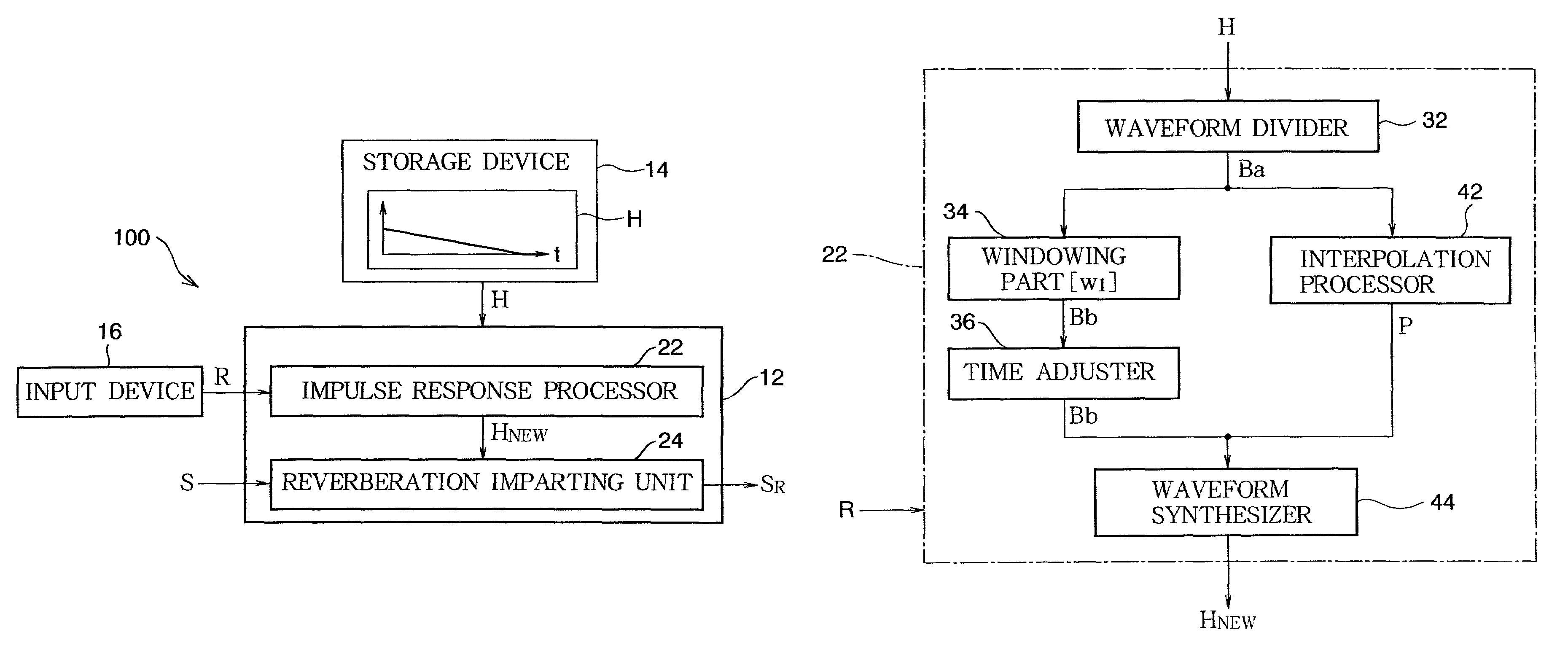
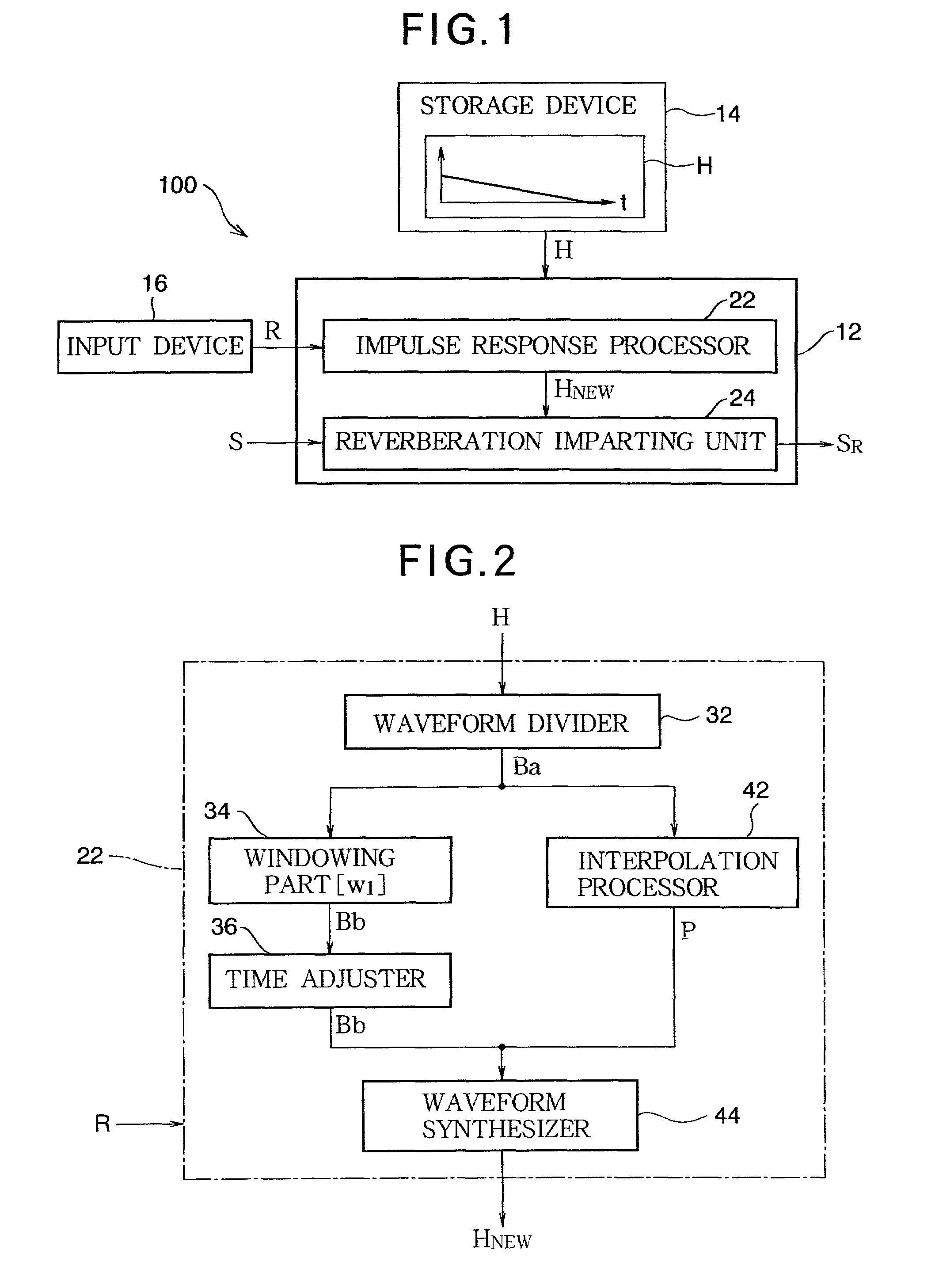
[0031]FIG. 1 is a block diagram of a reverberation imparting apparatus according to the first embodiment of the invention. A sound signal S representing the waveform of a (musical or vocal) sound is provided to a reverberation imparting apparatus 100. Examples of a sound source (not shown) that provides the sound signal S include a sound receiving device that generates a sound signal S according to an ambient sound or a playback device that sequentially acquires and outputs a sound signal S from a recording medium. The reverberation imparting apparatus 100 generates a reverberant sound signal SR by adding reverberation to the sound signal S and outputs the reverberant sound signal SR. The reverberant sound signal SR is provided to a sound emitting device (not shown) such as a speaker or headphones, which then reproduces the reverberant sound signal SR as a sound wave.

[0032]As shown in FIG. 1, the reverberation imparting apparatus 100 is a computer system that incl...

second embodiment

B: Second Embodiment

[0055]A description will now be given of the second embodiment of the invention. In the first embodiment, the waveform processor 54 reverses the waveform of the interpolation block Pa[i] generated by the averager 52 in the direction of the time axis. The waveform processor 54 of this embodiment generates an interpolation block Pb[i] by rotating the phase of the interpolation block Pa[i] generated by the averager 52. Elements in each of the following embodiments which are shared with the first embodiment are denoted by the same reference numerals and a detailed description thereof is appropriately omitted.

[0056]FIG. 8 is a block diagram of the waveform processor 54 in this embodiment. As shown in FIG. 8, the waveform processor 54 includes a converter 542, a phase shifter 544, and an inverse converter 546. The converter 542 converts the interpolation block Pa[i] into a signal of the frequency domain (i.e., a frequency spectrum), for example using Fourier transform....

third embodiment

C: Third Embodiment

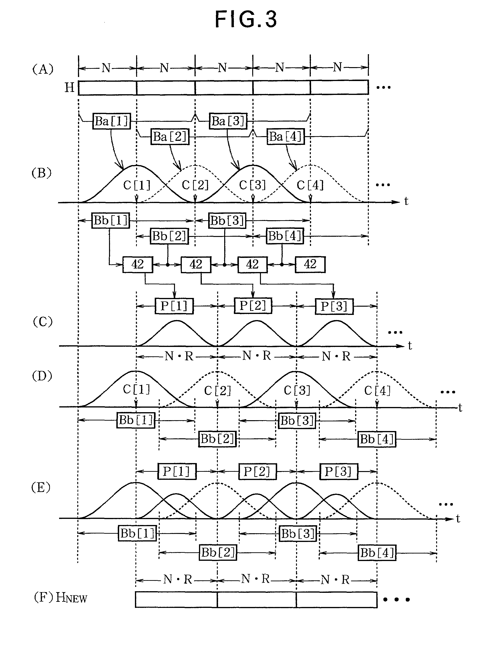
[0058]The following is a description of the third embodiment of the invention. In the first embodiment, it is assumed that the scaling factor R of the reverberation time is equal to or less than 2. One purpose of this embodiment is to extend the reverberation time by a scaling factor R of greater than 2. In the case where the scaling factor R is less than or equal to 2 in this embodiment, the reverberation time is extended through the same procedure as the first or second embodiment.

[0059]FIG. 9 is a conceptual diagram illustrating the operation of this embodiment. When the scaling factor R is greater than 2, for example when R=2.5, the interval (N·R) between the central points C[i] and C[i+1] of the base blocks Bb[i] and Bb[i+1] generated through adjustment of the time adjuster 36 is greater than a section of 2N samples of the impulse response H. Accordingly, the magnitude of a section corresponding to the interval between the base block Bb[i] and the base block ...


PUM


Abstract

An impulse response processing apparatus is composed of a waveform divider, a time adjuster, an interpolation processor and a waveform synthesizer. The waveform divider divides an impulse response into a plurality of base blocks on a time axis. The time adjuster increases a time difference between two adjacent ones of the plurality of the base blocks. The interpolation processor generates an interpolation block. The waveform synthesizer generates a new impulse response by arranging the interpolation block between the two adjacent base blocks generated through adjustment of the time adjuster.

Description

BACKGROUND OF THE INVENTION[0001]1. Technical Field of the Invention[0002]The present invention relates to a technology for processing an impulse response used to impart reverberation.[0003]2. Description of the Related Art[0004]A technology for changing a time length during which reverberation continues (which will be referred to as a “reverberation time”) in an apparatus for imparting reverberation to a sound signal through convolution of an impulse response has been suggested. For example, Japanese Patent Application Publication No. 2004-294712 describes a technology in which a new impulse response having a desired reverberation time is generated by summing (i.e., linearly combining) two types of impulse responses after multiplying each of the impulse responses by an exponential function.[0005]However, in the technology of Japanese Patent Application Publication No. 2004-294712, the magnitude of noise such as background noise superimposed on the impulse response is also amplified...

Claims


Application Information

Patent Timeline
Patent Type & Authority Patents(United States)
IPC IPC(8): H03G3/00
CPCG10K15/12
Inventor SHIRAKIHARA, FUTOSHI
Owner YAMAHA CORP
Why Eureka
Try Eureka