Zoom system for an optical stereo device

a stereo camera and optical stereo technology, applied in the field of zoom systems for stereo microscope systems or stereo cameras, can solve the problems of bulky optical devices and unaffordable elements, and achieve the effect of convenient gauge and small optical devices

Inactive Publication Date: 2012-02-14
FORSTGARTEN INT HLDG
View PDF14 Cites 2 Cited by
  • Summary
  • Abstract
  • Description
  • Claims
  • Application Information

AI Technical Summary

Benefits of technology

[0005]The zoom system according to the present invention provides for the advantage that the zoom system can be more easily gauged, because substantially each component thereof is readily accessible. Furthermore, control, drive and power supply units can be readily arranged within the zoom system itself, which, in turn, allows for the provision of smaller optical devices.

Problems solved by technology

A drawback of these conventional configurations is that the annular cam disk completely surrounds the optical system and the lenses thereof so that these elements are not readily accessible.
Furthermore, the conventional systems leave virtually no space for installing additional components, such as control, drive and power supply units, resulting in rather bulky optical devices.

Method used


Image

  • Zoom system for an optical stereo device
  • Zoom system for an optical stereo device
  • Zoom system for an optical stereo device

Examples


Embodiment Construction

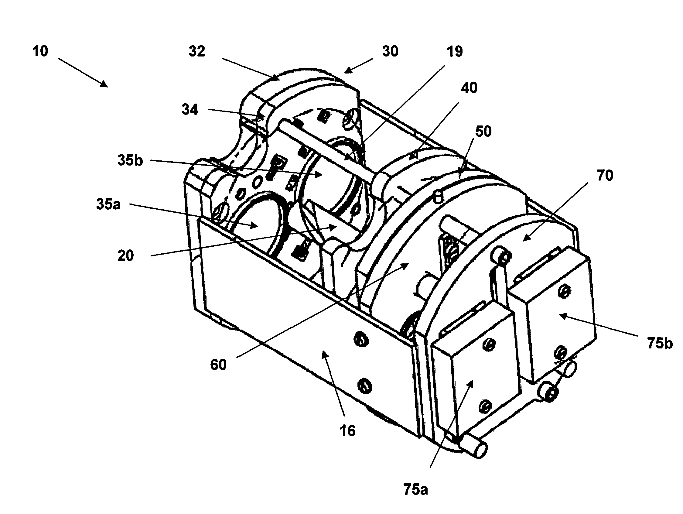
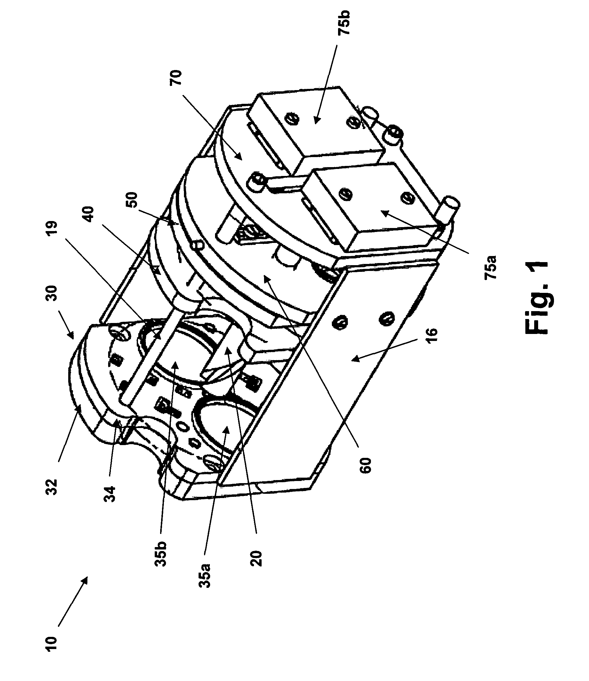
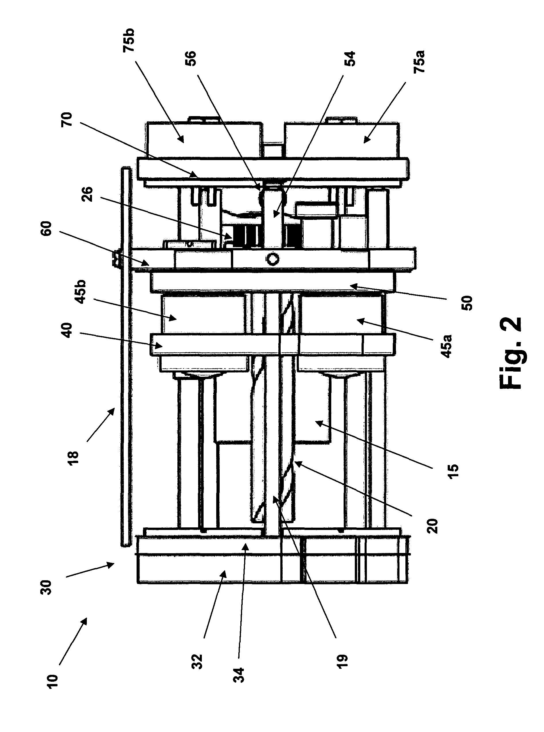
[0014]A preferred embodiment of a zoom system 10 for an optical stereo device, such as a stereo microscope or a stereo camera, and the components thereof are shown in FIGS. 1 to 6. The zoom system 10 provides for two optical paths for light entering the zoom system 10 through the lens assemblies 35a and 35b of the front plate 30 and being detected by optical detectors 75a and 75b mounted to a detector or rear plate 70 (see FIGS. 1 and 2). As will be discussed in more detail further below, the front plate preferably is a composite front plate 30. The optical detectors 75a and 75b could be CCD or CMOS devices for electronically acquiring and storing images, which, as the person skilled in the art is well aware of, can be read out and processed by means of a control unit, such as a CPU. Alternatively, in case the zoom system according to the present invention is employed within a stereo microscope the optical detectors 75a and 75b could be replaced by suitably arranged and configured e...


PUM


Abstract

A zoom system (10) for an optical stereo device is provided. The zoom system (10) comprises a front plate (30) and a lens plate (60) disposed in a fixed spatial relationship and defining two optical paths within the zoom system (10). The zoom system further comprises a zoom plate (40) having two lens assemblies (45a, 45b), wherein the zoom plate (40) is disposed between the front plate (30) and the lens plate (60), and a compensation plate (50), wherein the compensation plate (50) is disposed between the zoom plate (40) and the lens plate (60). The zoom system further comprises a drive spindle (20) having a helical groove and a cam disk portion for simultaneously adjusting the position of the zoom plate (40) and the compensation plate (50) relative to the front plate (30) and the lens plate (60) in a coordinated manner, wherein the position of the zoom plate (40) is adjusted by means of the helical groove and the position of the compensation plate is adjusted by means of the cam disk portion of the drive spindle (20).

Description

TECHNICAL FIELD OF THE INVENTION[0001]The invention relates to a zoom system for an optical stereo device and in particular to a zoom system for a stereo microscope system or a stereo camera to be employed by medical professionals and especially dentists and surgeons.BACKGROUND OF THE INVENTION[0002]In the medical field it is becoming more and more common practice to use stereo microscopes or cameras for assisting medical professionals in performing such tasks as medical surgeries, examinations, treatments and the like. Typically these optical devices provide for the possibility of zooming into a picture by means of a so-called pancreatic lens system. During zooming, some lenses of the pancreatic lens system are moved and must be brought into certain positions in relation to other fixed lenses with extraordinary precision in order to provide for a good image. Conventionally an annular cam disk milled with great care has been used to control the position of these lenses and thereby t...

Claims


Application Information

Patent Timeline
Patent Type & Authority Patents(United States)
IPC IPC(8): H04N5/262G02B27/22G03B3/00
CPCG02B7/102G02B21/025G02B21/22
Inventor LUBER, JOACHIM
Owner FORSTGARTEN INT HLDG
Why Eureka
Try Eureka