
Apparatus and method for mapping hair metric

a technology of hair loss and applicability, applied in the field of applicability and method of mapping hair loss, can solve problems such as difficult comparison of hair loss status

Inactive Publication Date: 2012-02-14
RASSMAN WILLIAM
View PDF10 Cites 11 Cited by
  • Summary
  • Abstract
  • Description
  • Claims
  • Application Information

AI Technical Summary

Benefits of technology

[0020]The present invention is based on the recognition that a metric for hair loss can be produced by imaging areas of any hair bearing skin which are sufficiently large (i.e. 50,000 square millimeters of the human scalp) that the focal areas can be later revisited reliable where any offset in positioning would introduce only acceptably small errors. A map of the hair bearing skin or scalp can be generated by a compilation of the images to provide a reliable metric of hair loss status for comparison with the metrics previously generated.
[0021]The invention provides a method and apparatus for geographically mapping user defined locations of hair bearing skin area with a bulk metric output. The metric values may be used to compare different user defined locations to quantify relative differences by location. The metric values may also be used to compare user defined locations at different time intervals to quantify relative differences over a period of time. The mapping and the metrics can be achieved more specifically by automated means by the analysis of multiple static pictures or the analysis of a live video covering a larger area than a single, static field of view. It also provides a method and apparatus for sorting and characterizing the relative diameter of a hair shaft by automated means in which the total cross sectional area of all the hair shafts in the interrogated field can be calculated. The automated method of obtaining this metric can be effectively used to acquire the bulk of hair over user defined locations and time intervals.
[0024]In effect, this automation produces metrics for Density (D) and Miniaturization (M). It also provides metrics for the bulk (B) of hair that is expressed as the total cross sectional area occupied by hair divided by the area under interrogation. This provides a quantifiable value in assessing the state of hair density, miniaturization, and bulk for the purpose of diagnosis. The variation of (M), (D), and (B) over different location and at different times will provide valuable information to the end user for the diagnosis and progression of hair loss or hair gain. The pattern of hair loss can also be determined with the aforementioned metrics. It is this ability to map out a metric based system for the status of hair loss at multiple locations sufficiently large to be accurately revisited and in a relatively short time window (seconds or minutes) that is the essence of this invention. When longer time intervals are used (weeks. months and years) an assessment of change in hair bulk can be measured. This method and apparatus would be particularly useful for documentation of hair loss or gain progression over time and / or hair gains in bulk after treatment regimens have had time to work. Drugs like finasteride (Propecia) are but one example of such a treatment regimen.
[0025]Another embodiment of the invention consists of a hand held device which a user moves from front to back along the scalp to establish a path of sufficient size to permit accurate measurements. The end user points the sensor end to the location of interest to obtain readings as the sensor is moved. The bulk of hair may be expressed in many ways depending on the aforementioned metrics and may incorporate the cross sectional area the hair shafts occupy in a field of interrogation. In this particular embodiment, a relative ‘hair bulk’ number may be expressed so that the end user can compare the value to the value at other locations or compare the value to other references on the individuals anatomy over time. This embodiment would conveniently have a recording and analysis function to keep track of the different data and reference points with dimensional locations mapped out. It could represent various static images or a ‘video like’ device that enables a person to sweep the hair bearing area along a series of tracks in a pattern that will, in effect, produce a more detailed map of hair bulk in the scalp, by area. In practice the device may be adapted to keep track of the velocity of movement and reference of a user defined location and record the time of data acquisition.

Problems solved by technology

The prior art systems, even those employing imaging systems, determine the status of hair loss that is difficult to compare at different time intervals because the area of interrogation is not well defined geographically.

Method used


Image

  • Apparatus and method for mapping hair metric
  • Apparatus and method for mapping hair metric
  • Apparatus and method for mapping hair metric

Examples


Embodiment Construction

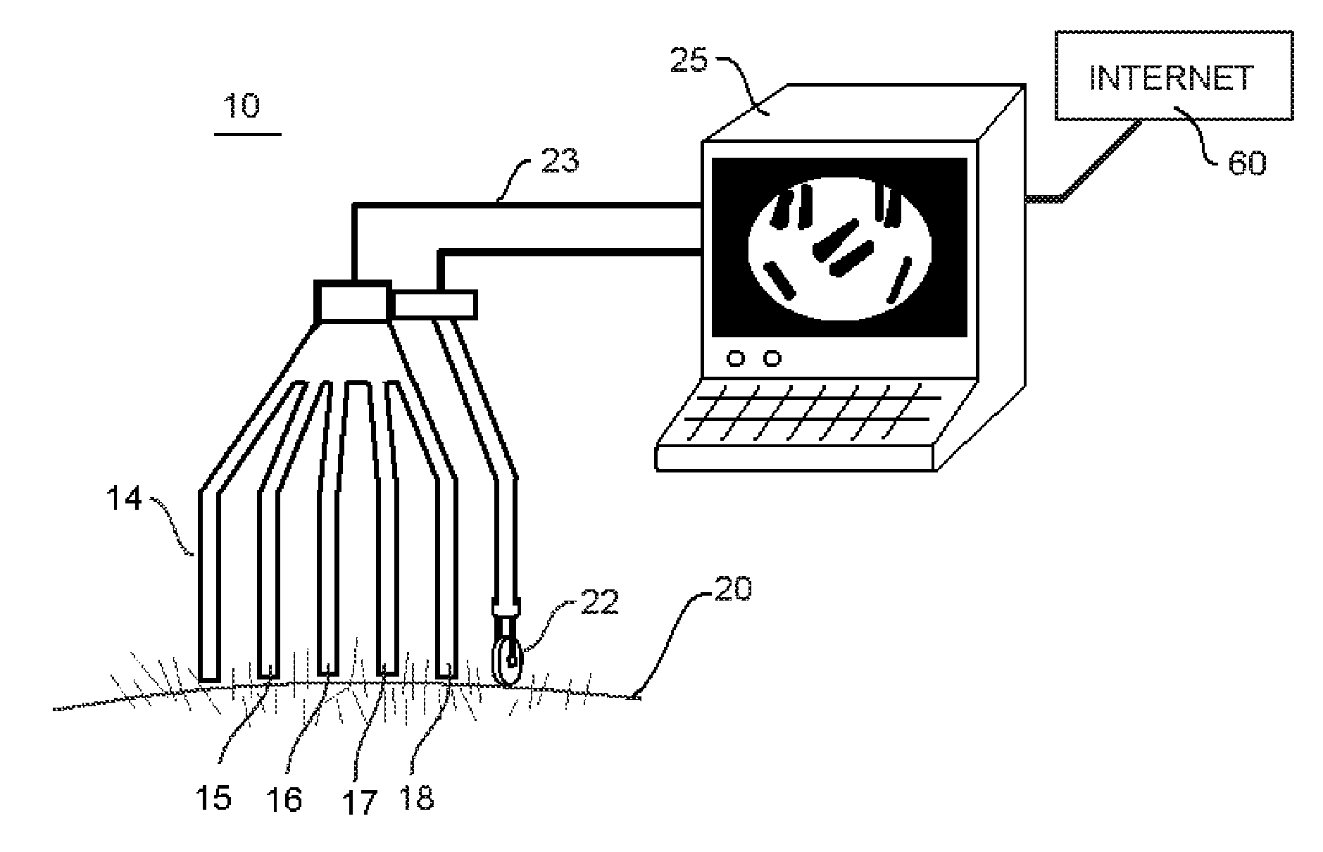
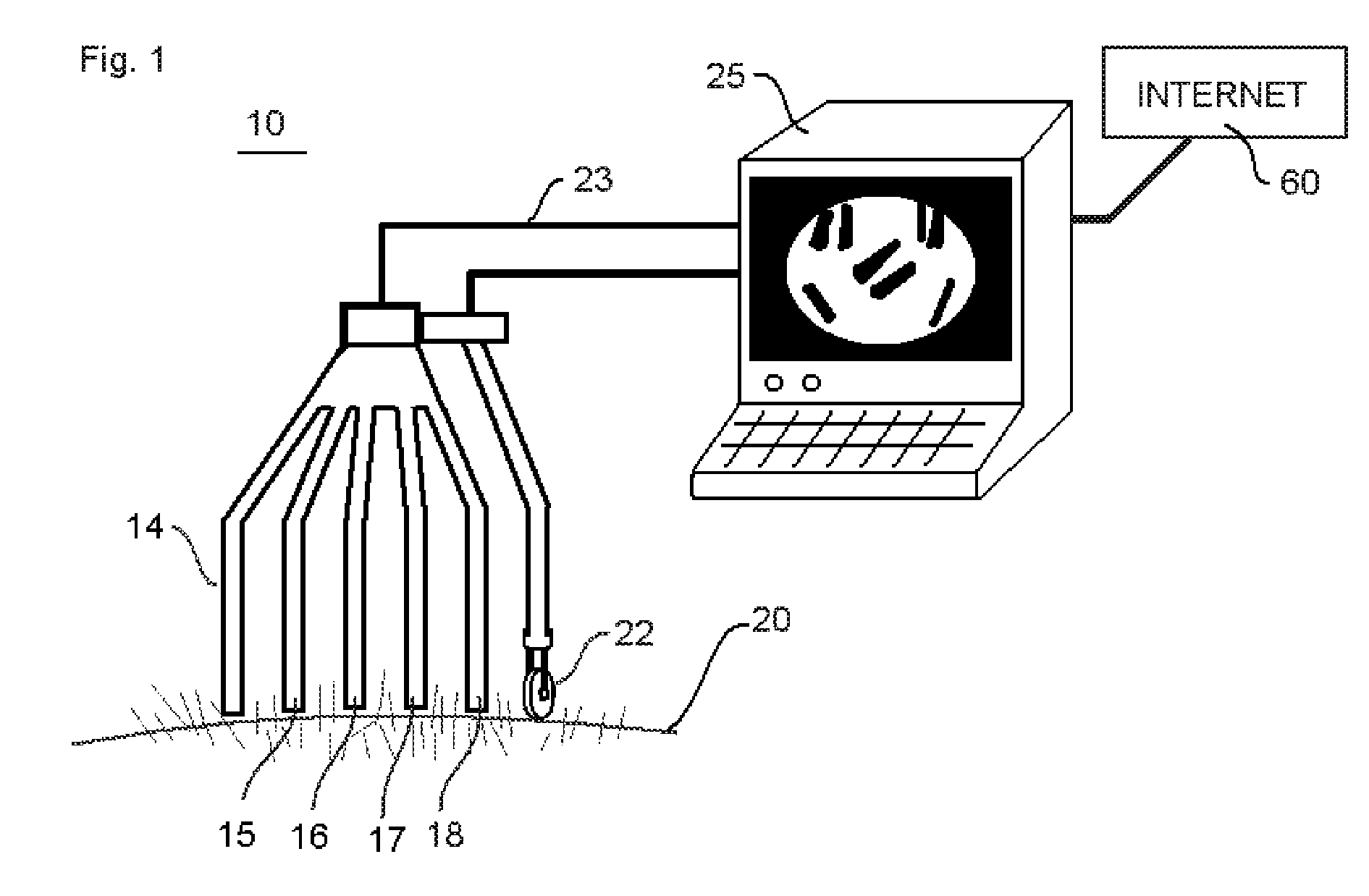
[0028]FIG. 1 is a schematic representation of a system embodiment of this invention showing the image capture apparatus;

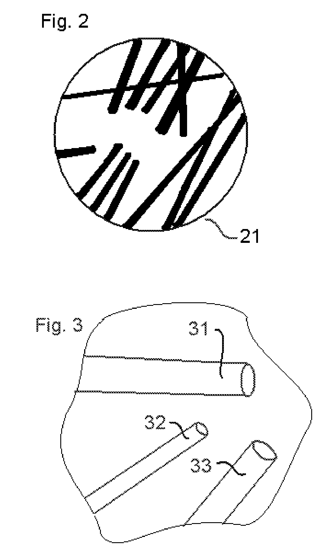
[0029]FIGS. 2, 3, and 4 are schematic fields of view with the apparatus of FIG. 1 showing illustrative views of portions of the scalp or hair bearing skin;

[0030]FIG. 5 is a flow diagram of the operation of the system of FIG. 1 responsive to field of view images of the type shown in FIGS. 2, 3, and 4;

[0031]FIG. 6 is a schematic view of a scalp or hair bearing skin with imaginary path and geography indicators as a reference for establishing grid indicia for location revisiting during sequential valuations; and

[0032]FIG. 7 is a handheld embodiment in accordance with the principles of this invention.

[0033]FIG. 8 shows an embodiment of the metric data representation between two time intervals.

DETAIL DESCRIPTION OF ILLUSTRATIVE EMBODIMENTS OF THIS INVENTION

[0034]Apparatus in accordance with the principles of this invention contains a digital recording device (camera), a ...


PUM


Abstract

Apparatus for determining the status of hair bulk in an area of a scalp is operative to provide a metric over a sufficiently large area to permit revisiting with only negligible misalignment error. Accurate re-measurement of hair status in accurately identified areas produces a reliable metric for determining degree of hair loss and or the effectiveness of treatment.

Description

RELATED APPLICATIONS[0001]The present application is related to U.S. Pat. No. 5,331,472 issued Jul. 19, 1994 included by reference herein.[0002]The present application is related to U.S. Pat. No. 6,253,771 issued Jul. 3, 2001 included by reference herein.[0003]The present application is related to U.S. Pat. No. 4,807,163 issued Feb. 21, 1989 included by reference herein.[0004]The present application is related to U.S. Pat. No. 7,098,910 issued Aug. 29, 2006 included by reference herein.[0005]The present application is related to U.S. Pat. No. 7,006,657 issued Feb. 28, 2006 included by reference herein.[0006]The present application is related to U.S. Pat. No. 6,993,851 issued Feb. 7, 2006 included by reference herein.FIELD OF THE INVENTION[0007]This invention relates to geographically mapping the characteristics of hair over a user defined areas of hair bearing skin and comparing the relative metrics between the aforementioned areas in four dimensions of time and space.BACKGROUND OF ...

Claims


Application Information

Patent Timeline
Patent Type & Authority Patents(United States)
IPC IPC(8): A61B1/00G06K9/00
CPCA61B5/448A61B5/1072
Inventor RASSMAN, WILLIAMPAK, JAE P
Owner RASSMAN WILLIAM
Learn More