Image recording device

a recording device and image technology, applied in the direction of typewriters, hammer-impression mechanisms, type-actuating printing mechanisms, etc., can solve the problems of affecting the sequence of switch timing between the driving units, the structure of the transmission mechanism for transmitting a driving force from a single motor to a plurality of driving units becomes inevitably complicated, and the nozzle ejection condition occurs in the ejection motion of the nozzl

Active Publication Date: 2012-02-07
BROTHER KOGYO KK
View PDF17 Cites 2 Cited by
  • Summary
  • Abstract
  • Description
  • Claims
  • Application Information

AI Technical Summary

Benefits of technology

[0016]Aspects of the present invention are advantageous in that an image recording device capable of engaging a plurality of switch gears with transmission gears quickly and reliably is provided.
[0018]In the above described configuration, an overlapping drive period in which the first and the second motors are driven concurrently can be secure. Therefore, it is possible to release a surface pressure acting on gears and, for at least one of the motors, it is possible to move the switch gear and the transmission gear to the state of being able to engage with each other at a low speed period of the corresponding motor (i.e., a state immediately after activation of the motor). Consequently, it becomes possible to engage each switch gear to a corresponding transmission gear rapidly and securely before the speed of each motor increases.

Problems solved by technology

There is a possibility that a faulty ejection condition occurs in the ejecting motion of the nozzles, for example, due to air bubbles caused in the nozzles or foreign material lodging in the nozzles.
If a plurality of driving units are provided in the image recoding device, a structure of a transmission mechanism for transmitting a driving force from a single motor to the plurality of driving units becomes inevitably complicated.
Furthermore, the sequence of switch timing between the driving units becomes complicated.
This might cause a problem that a time for switching a transmission gear to another desired transmission gear becomes too long.
However, the switch gears and the transmission gears are not always located at positions where the switch gears are able to engage with respective transmission gears.
For this reason, even if the switch gears are moved concurrently in a moving direction, each switch gear might not be able to properly engage with the transmission gear.
Furthermore, due to a surface pressure between gears provided between the driving unit and the transmission gear, the switch gear might become unable to move in the axial direction, and thereby the switch gear and the transmission gear might become unable to engage with each other.
However, if the plurality of motors are controlled to reciprocate in a careless way, each switch gear can not be switched between the transmission gears.
For example, if a pair of gears are brought to a state of being able to engage with each other, the other pair of gears might become unable to engage with each other due to excessively increased rotation speed of the motor.
Furthermore, even if the plurality of motors are alternatively driven in the state where switch gears engage with respective transmission gears, both of the switch gears are not able to move concurrently due to the surface pressure when one of the switch gears is stopped.

Method used


Image

  • Image recording device
  • Image recording device
  • Image recording device

Examples


Embodiment Construction

[0037]Hereafter, an embodiment according to the invention will be described with reference to the accompanying drawings.

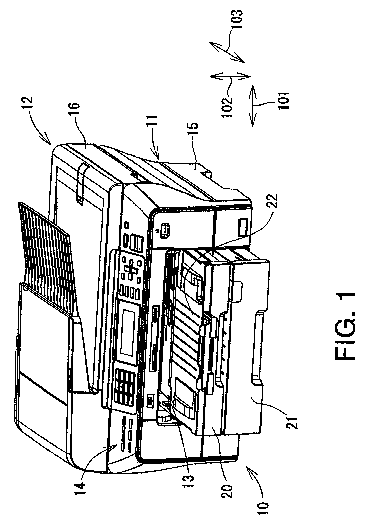
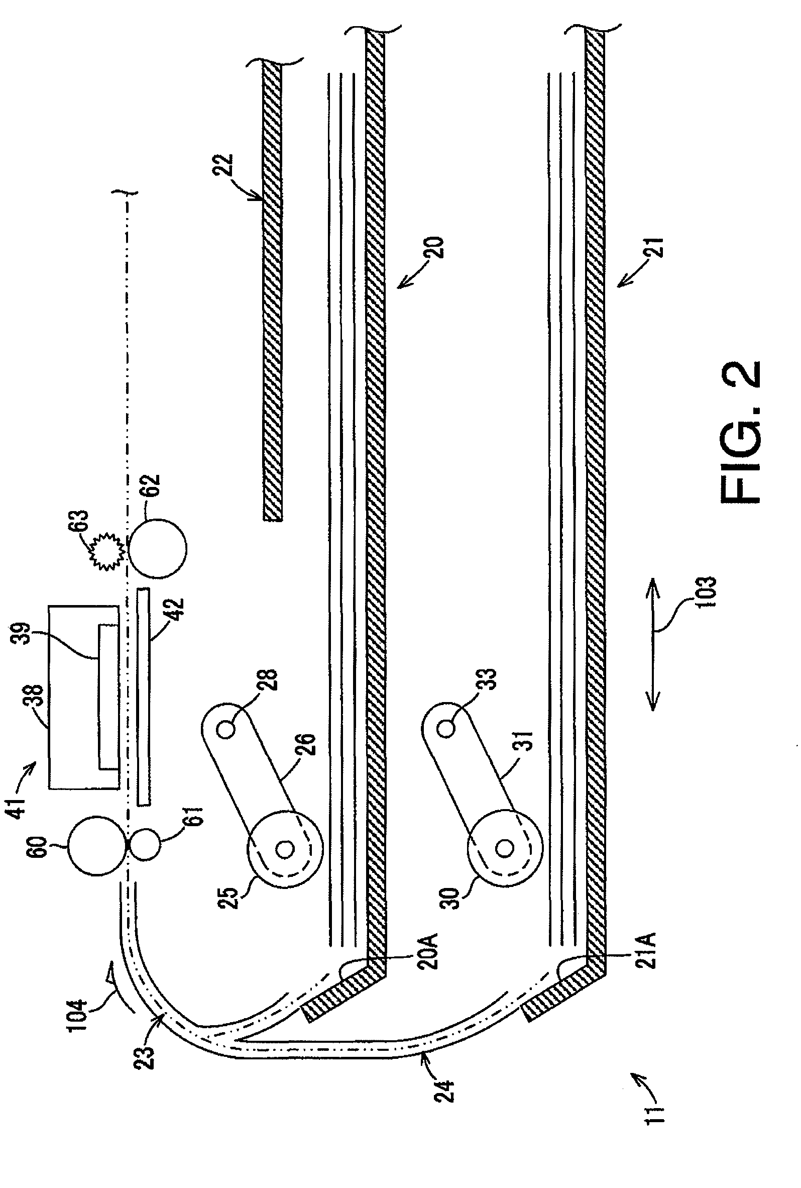
[0038]FIG. 1 is a perspective view illustrating an outer appearance of an MFP (Multifunction Peripheral) 10 according to an embodiment. FIG. 2 is a cross sectional view illustrating an internal structure of a print unit 11 provided in the MFP 10. FIG. 3 is a perspective view of the internal structure of the print unit 11 when viewed from the rear side.

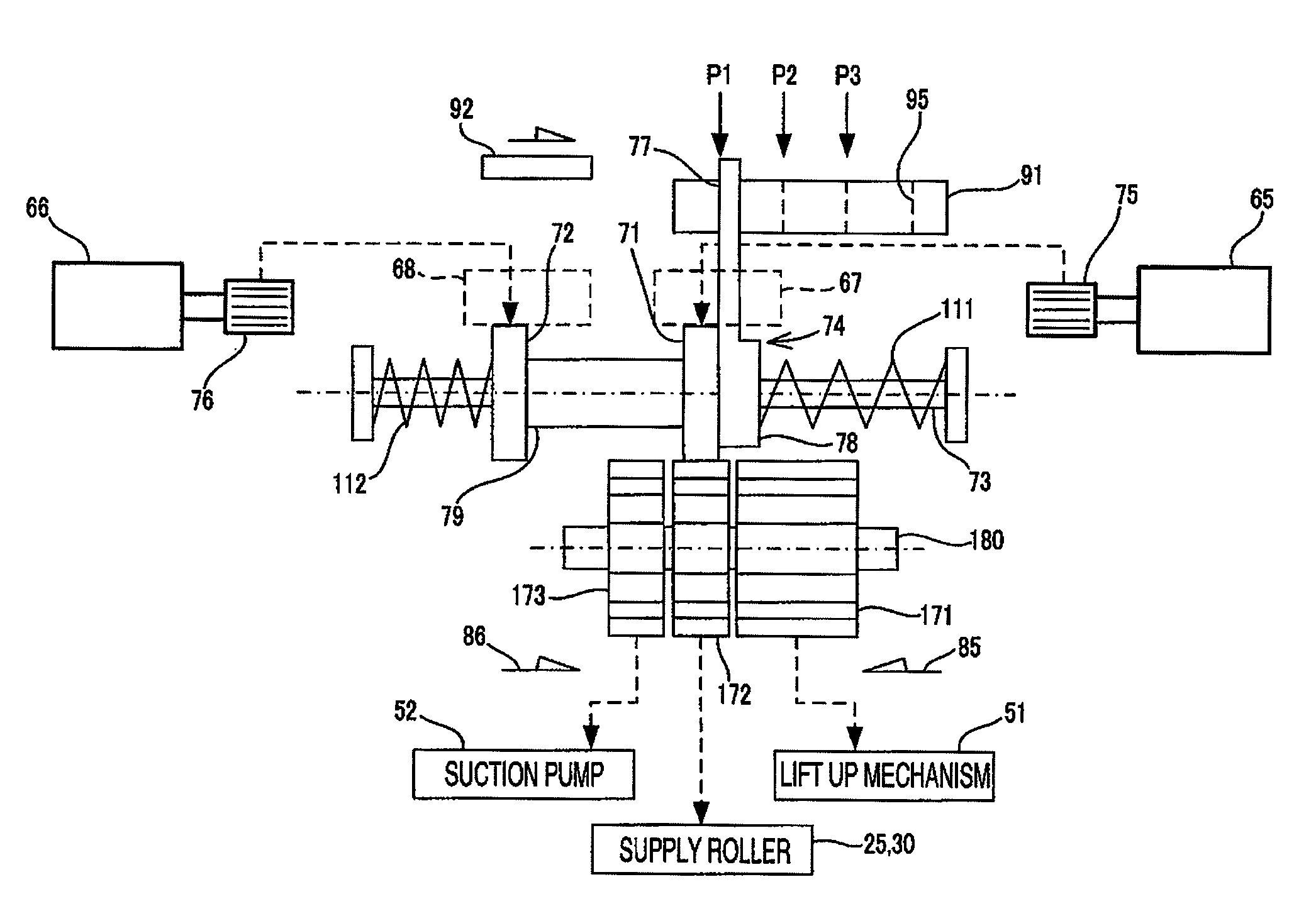
[0039]FIG. 4 is a perspective view illustrating a drive switch mechanism 70. FIG. 5 schematically illustrates a structure of a gear unit 110 and a transmission path. FIGS. 6A to 6C are explanatory illustrations for explaining positions of an input lever 74 and motion of the gear unit 110. FIGS. 7A and 7B are explanatory illustrations for explaining malfunctions of the gear unit 110.

[0040]FIG. 8 is a block diagram of a motor control unit 130. FIG. 9 is a flowchart illustrating a motor control process executed by the mo...


PUM


Abstract

There is provided an image recording device, comprising first and second motors; first and second switch gears supported coaxially; first and second transmission gears, and wherein the first and second switch gears are provided to engage with corresponding ones of the first and second transmission gears in accordance with movement of the first and second switch gears in an axial direction, and the image recording device further comprises a control unit configured such that when the first switch gear and the second switch gear are moved in the axial direction, the control unit rotates one of the first and second motors by a first predetermined rotation amount, and starts the other of the first and second motors while the one of the first and second motors is rotated. The control unit rotates the other of the first and second motors by a second predetermined rotation amount.

Description

CROSS-REFERENCE TO RELATED APPLICATION[0001]This application claims priority under 35 U.S.C. §119 from Japanese Patent Application No. 2008-104137, filed on Apr. 11, 2008. The entire subject matter of the application is incorporated herein by reference.BACKGROUND[0002]1. Technical Field[0003]Aspects of the present invention relate to an image recording device provided with a switch mechanism which switches a driving force between transmission gears connected to drive mechanisms by changing positions of switch gears connected to a motor.[0004]2. Related Art[0005]Conventionally, image recording devices, such as an inkjet printer, have been widely used. The inkjet printer records an image on a recording medium by ejecting ink in accordance with an input signal. More specifically, in the inkjet printer, ink is introduced to actuators in a recording head, and the ink is pressurized and ejected through the effect of deformation of the actuators or the effect of locally boiled ink by heati...

Claims


Application Information

Patent Timeline
Patent Type & Authority Patents(United States)
IPC IPC(8): B41J29/38B41J2/165B41J11/18B41J7/00
CPCB41J11/485B41J29/38
Inventor SAMOTO, KENJIKOGA, YUJI
Owner BROTHER KOGYO KK
Why Eureka
Try Eureka