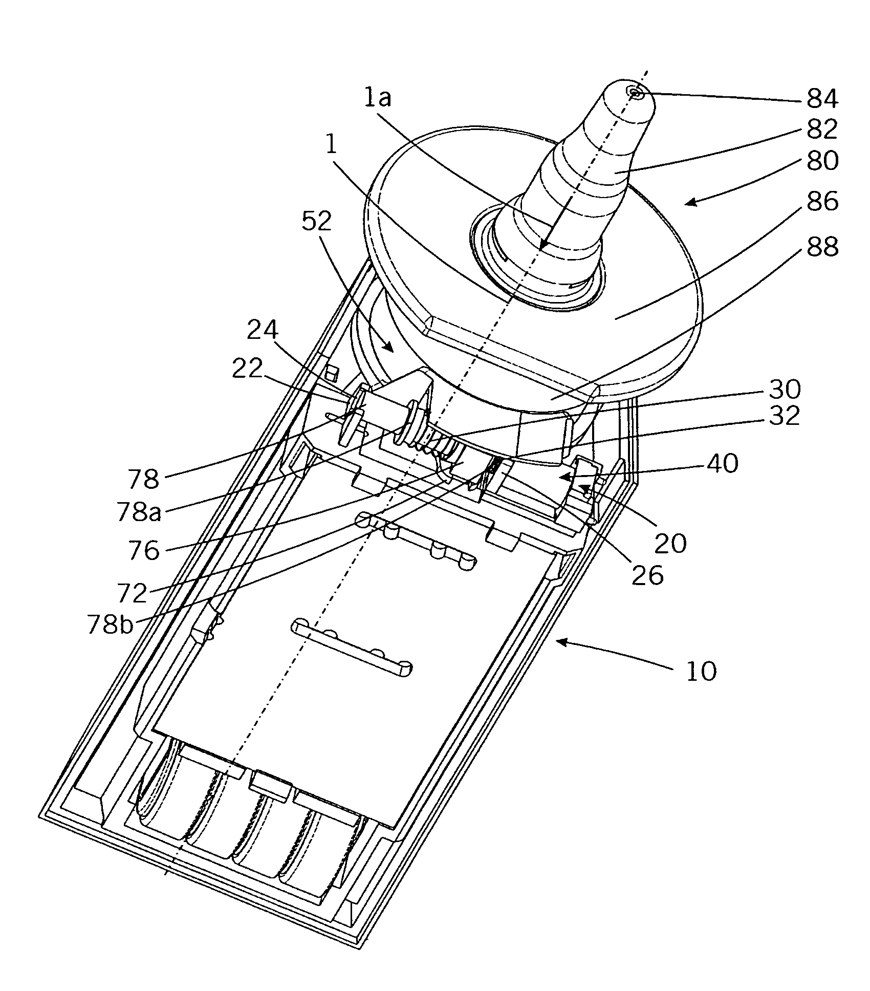
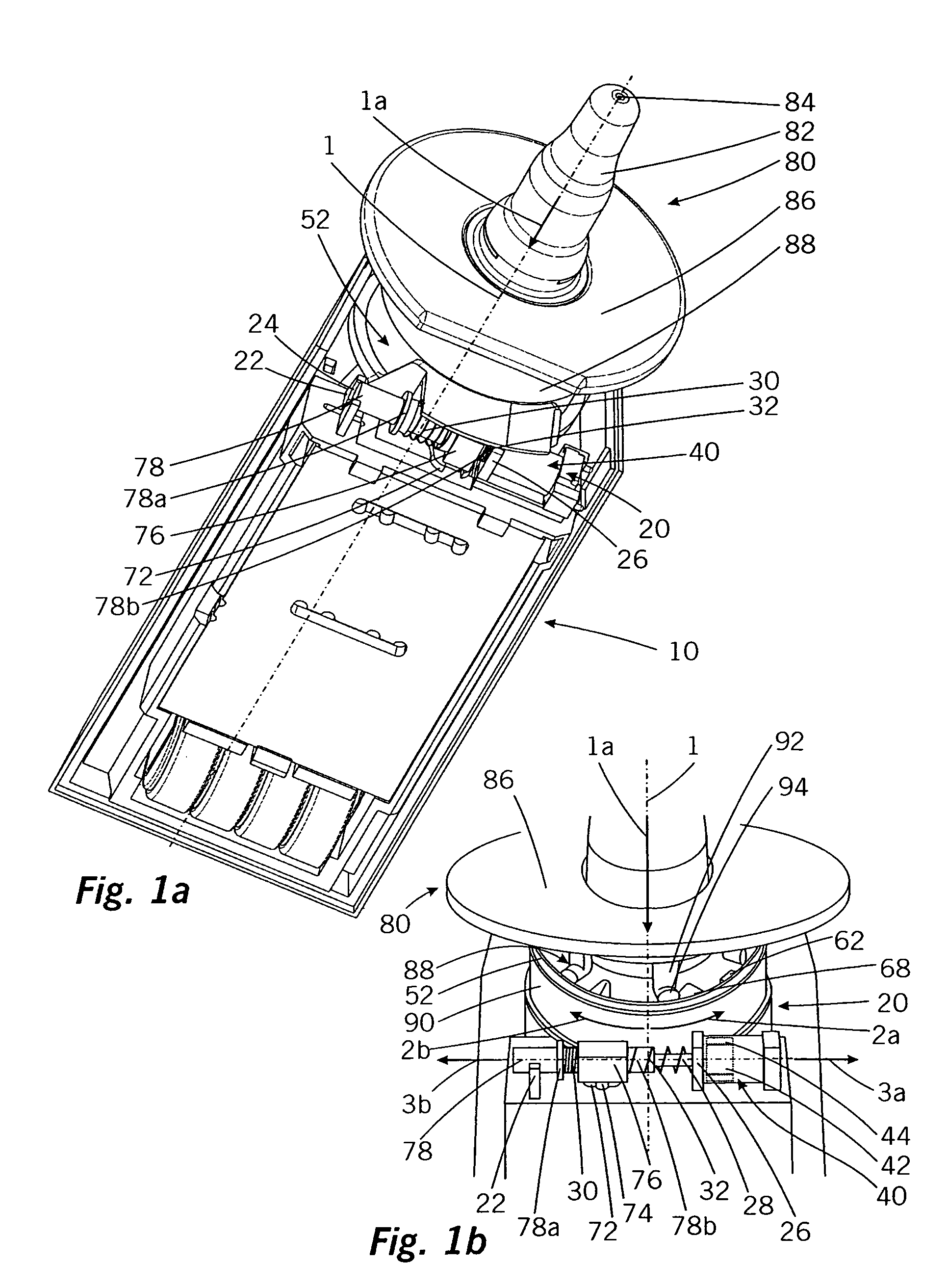
Discharge device
a discharge device and discharge technology, applied in the direction of liquid handling, applications, instruments, etc., can solve the problems of a number of difficulties in the discharge device of the prior art, and have not been completely solved
- Summary
- Abstract
- Description
- Claims
- Application Information
AI Technical Summary
Benefits of technology
Problems solved by technology
Method used
Image
Examples
second embodiment
[0106]In the locked state of FIG. 8a an operation of the discharge device is impossible for the reasons given in connection with the embodiment of FIGS. 1 to 5. On pressing down the operating member 188, the cams of the operating member 188 not shown in conjunction with this second embodiment would be prevented by the locking sections of locking member 152 from a displacement necessary for a discharge process.
[0107]Only on energizing electromagnet 147 through the not shown control electronics is it possible to bring about the release state of the discharge device. Energization of electromagnet 147 leads to a brief force actuation of the bolt auxiliary member 144 to the right in direction 5b. The force actuation by electromagnet 147 need not be very powerful, because it only needs together with the force actuation by the spring clip 148 on the bolt auxiliary member 144 to overcome the holding force in the opposite direction provided by permanent magnet 146. The displacement of the bo...
first embodiment
[0108]The state of FIG. 8b represents the resulting release state of the discharge device. Through the displacement of the push rod component 178 there has also been a rotation of locking member 152 in direction 2b, so that said locking member 152 is now in a position in which the cams of operating member 188 can be moved past the locking sections of locking member 152 so as to enable a discharge process. This corresponds to the state of FIGS. 3a to 3c of the
[0109]As has already been described relative to the first embodiment, the discharge process within the scope of the stroke and return stroke movements once again leads to a rotation of locking member 152 in the direction of arrow 2a. As a result of the forcible coupling of locking member 152 with push rod component 178 the latter is also moved in the direction of arrow 6b. In a first partial portion said movement initially has no consequences regarding the position of bolt 142. Only when locking cam 175 has come into the vicinit...
PUM
 Abstract
Description
Claims
Application Information
 - R&D
- Intellectual Property
- Life Sciences
- Materials
- Tech Scout
- Unparalleled Data Quality
- Higher Quality Content
- 60% Fewer Hallucinations
Browse by: Latest US Patents, China's latest patents, Technical Efficacy Thesaurus, Application Domain, Technology Topic, Popular Technical Reports.
© 2025 PatSnap. All rights reserved.Legal|Privacy policy|Modern Slavery Act Transparency Statement|Sitemap|About US| Contact US: help@patsnap.com


