Powering unit with full bridge and wide adjusting range circuit

a powering unit and wide adjustment range technology, applied in the field of powering units, can solve the problems of more difficult design of discharge circuits for current and voltage peak restriction, and achieve the effect of reducing the input-side and output-side filters

Inactive Publication Date: 2012-01-31
SIEMENS AG
View PDF11 Cites 2 Cited by
  • Summary
  • Abstract
  • Description
  • Claims
  • Application Information

AI Technical Summary

Benefits of technology

[0010]This arrangement of two secondary branches allows a significant reduction in the voltage difference dropping at the resistors within the critical upper input voltage range. The discharged energy of the voltages peaks produced by the switching processes is divided onto the two discharge circuits and thus reduces the charge of the capacitors in the discharge circuits. Less energy is thus lost in the two resistors and the level of efficiency of the powering unit increases.
[0012]It is however also advantageous if two transformers are provided in each instance with a primary winding and a secondary winding and each of the two primary windings is connected to the direct current voltage input by way of a full bridge circuit. The use of two transformers allows the current ripple of the current through the input choke coil and the current ripple of the current through the output choke coil to be significantly less, thereby allowing for a significant reduction in the input-side and output-side filter.
[0013]It is also advantageous if the at least one full bridge circuit consists of four switches and if an electronic controller is provided for controlling said switches. The switches can then be controlled using a phase shift modulation, with it being possible to modulate the dead time.

Problems solved by technology

For full bridge converters having an input voltage range for connection to alternative energy generators for instance (fuel cells, photovoltaic elements), the design of a discharge circuit for current and voltage peak restriction is more difficult.

Method used


Image

  • Powering unit with full bridge and wide adjusting range circuit
  • Powering unit with full bridge and wide adjusting range circuit
  • Powering unit with full bridge and wide adjusting range circuit

Examples


Embodiment Construction

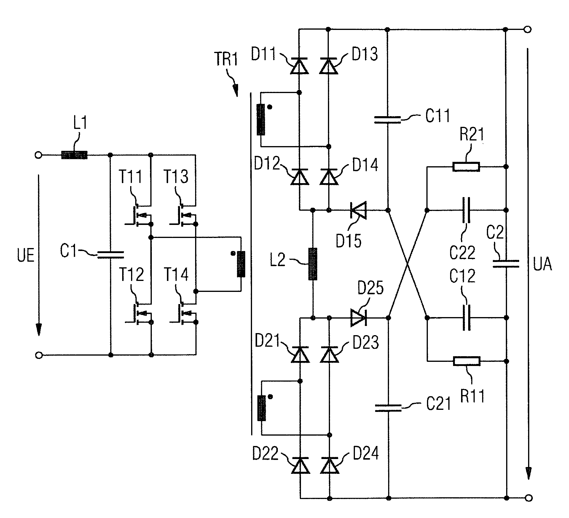
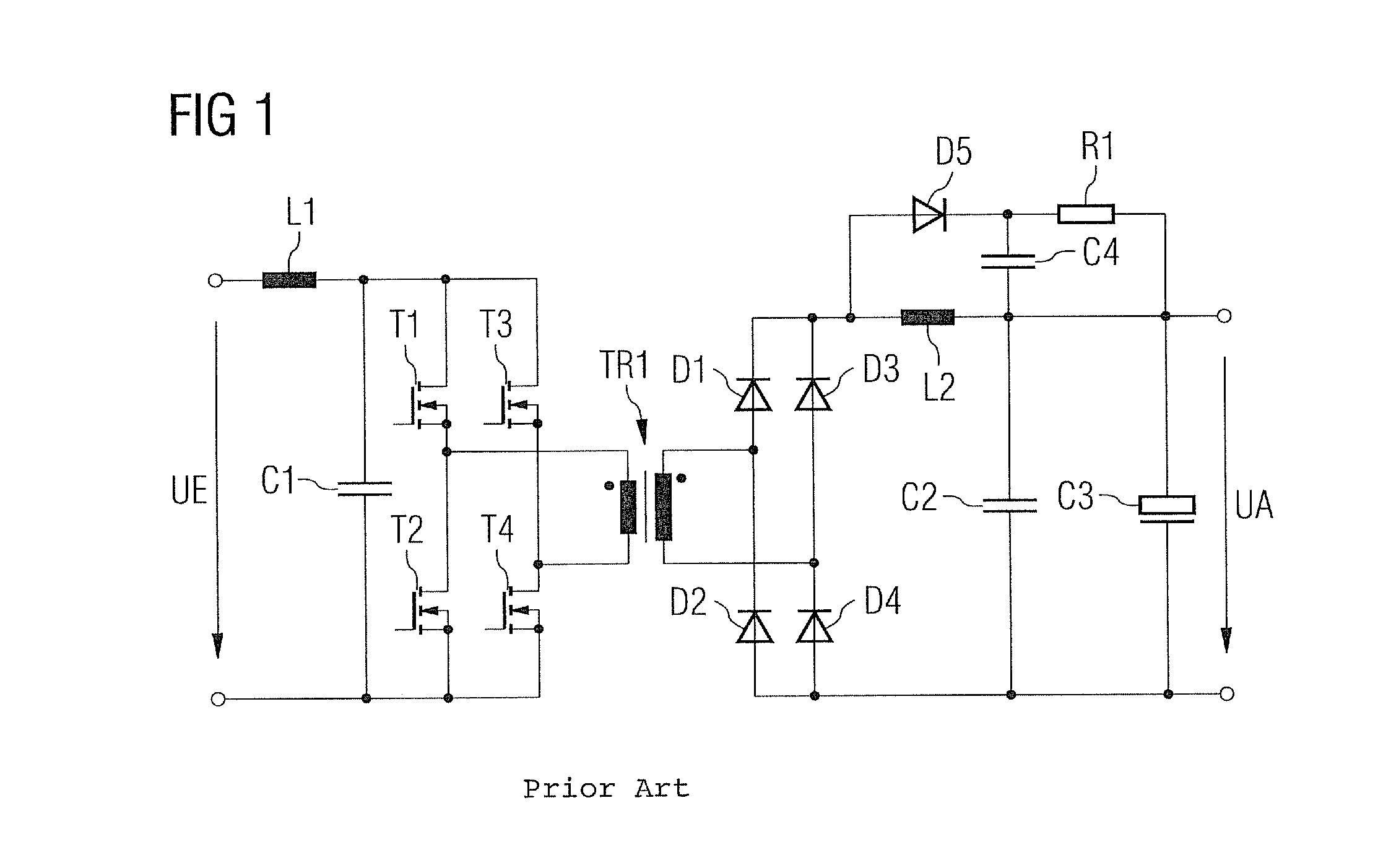
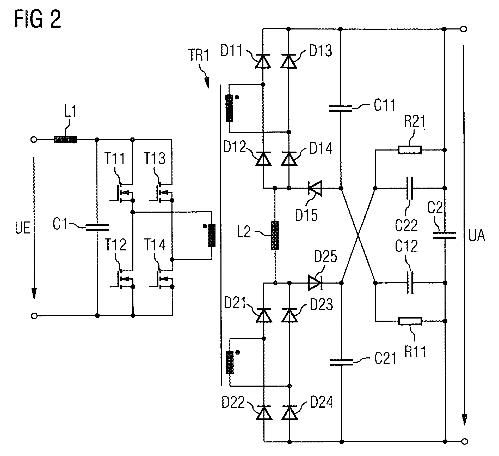
[0019]FIG. 1 shows a powering unit as a full bridge converter having a secondary-side discharge circuit according to the prior art. On the primary side, a full bridge including four transistors T1, T2, T3 and T4 is connected to a direct current voltage input UE via an input choke coil L1 and an input capacitor C1. The outputs of the full bridge are connected to a primary winding of a transformer TR1. On the secondary side, a secondary winding wound in the same direction is arranged on the transformer TR1, to which secondary winding a bridge-type rectifier circuit is connected. The bridge-type rectifier circuit includes four diodes D1, D2, D3 and D4. An output circuit with an output direct current voltage UA is triggered via an output choke coil L2 and two output capacitors C2 and C3. The second output capacitor C2 is embodied here by way of example as a poled electrolyte capacitor.

[0020]Also arranged on the secondary side is a discharge circuit having a diode D5, a capacitor C4 and ...


PUM


Abstract

There is described a powering unit comprising at least one transformer, at least one full bridge circuit via which a primary winding of the transformer is connected to a direct current voltage input, a secondary winding for triggering an output circuit with an output direct current voltage via a bridge-type rectifier circuit as well as an output choke coil and an output capacitor, and a discharge circuit consisting a diode, for a capacitor and of a resistor for reducing the secondary-side peak voltages. The powering unit has another secondary winding, another bridge-type rectifier circuit and another discharge circuit operable to trigger the output circuit with part of the output direct current voltage via the output choke coil and the output capacitor. Thus, there are fewer losses in the resistors and the performance is enhanced.

Description

CROSS REFERENCE TO RELATED APPLICATIONS[0001]This application is the US National Stage of International Application No. PCT / EP2006 / 062704, filed May 30, 2006 and claims the benefit thereof. The International Application claims the benefits of German application No. 10 2005 030 601.2 DE filed Jun. 30, 2005, both of the applications are incorporated by reference herein in their entirety.FIELD OF INVENTION[0002]The invention relates to a powering unit comprising at least one transformer, at least one full bridge circuit via which a primary winding of the transformer is connected to a direct current voltage input and a secondary winding for triggering an output circuit with a direct current voltage output via a bridge-type rectifier circuit as well as an output choke coil and an output capacitor, and a discharge circuit consisting of a diode, a capacitor and a resistor for reducing secondary-side peak voltages.BACKGROUND OF INVENTION[0003]The number of different designs of powering unit...

Claims


Application Information

Patent Timeline
Patent Type & Authority Patents(United States)
IPC IPC(8): H02M3/335H02H7/122
CPCH02M1/14
Inventor CESNAK, LORANDKOGARD, MARKUS
Owner SIEMENS AG
Why Eureka
Try Eureka