
Method for detecting molecular analysis light, and apparatus and sample plate for use with the same

a molecular analysis and light detection technology, applied in the direction of optical radiation measurement, instruments, spectrometry/spectrophotometry/monochromators, etc., can solve the problems of inability to limit the illumination area in the optical path direction, the cost of the entire apparatus, and the inability to limit the illumination area. , to achieve the effect of small measurement area and high sensitivity

Active Publication Date: 2012-01-31
FUJIFILM CORP
View PDF11 Cites 9 Cited by
  • Summary
  • Abstract
  • Description
  • Claims
  • Application Information

AI Technical Summary

Benefits of technology

[0014]In view of the above-described circumstances, the present invention is directed to providing a molecular analysis light detection method which allows detection of fluorescence from a small measurement area inexpensively and with very high sensitivity. The invention is also directed to providing and a molecular analysis light detection apparatus for use with the method, and a sample plate.
[0023]The enhancing member may be one that produces an electric field enhancing field on the surface thereof by generating a non-propagating electromagnetic wave, such as surface plasmon or localized plasmon, when exposed to the excitation light. However, the enhancing member may be made of any material that provides the effect of enhancing the light at the area provided with the enhancing member relative to the light at other areas at which no enhancing member is provided.

Problems solved by technology

However, since the objective lens with a NA that is high enough to detect the molecular fluorescence in the small volume is very expensive, the entire apparatus becomes expensive.
With the laser illumination, the illumination area in the in-plane direction can sufficiently be reduced by the high-NA objective lens, however, the illumination area in the optical path direction cannot be limited, and fluorescent bodies that moving in and out of the optical axis are excited.
Therefore, using this evanescent illumination, the depth of the area for exciting the fluorescence along the optical axis direction (z-axis direction) can be limited without providing the pinhole.
In these microscope apparatuses, however, sufficient sensitivity for allowing the single-molecule measurement is not obtained.
Since the objective lens having the NA high enough to detect the molecular fluorescence in the small volume is very expensive, the entire apparatus becomes expensive.

Method used


Image

  • Method for detecting molecular analysis light, and apparatus and sample plate for use with the same
  • Method for detecting molecular analysis light, and apparatus and sample plate for use with the same
  • Method for detecting molecular analysis light, and apparatus and sample plate for use with the same

Examples


first embodiment

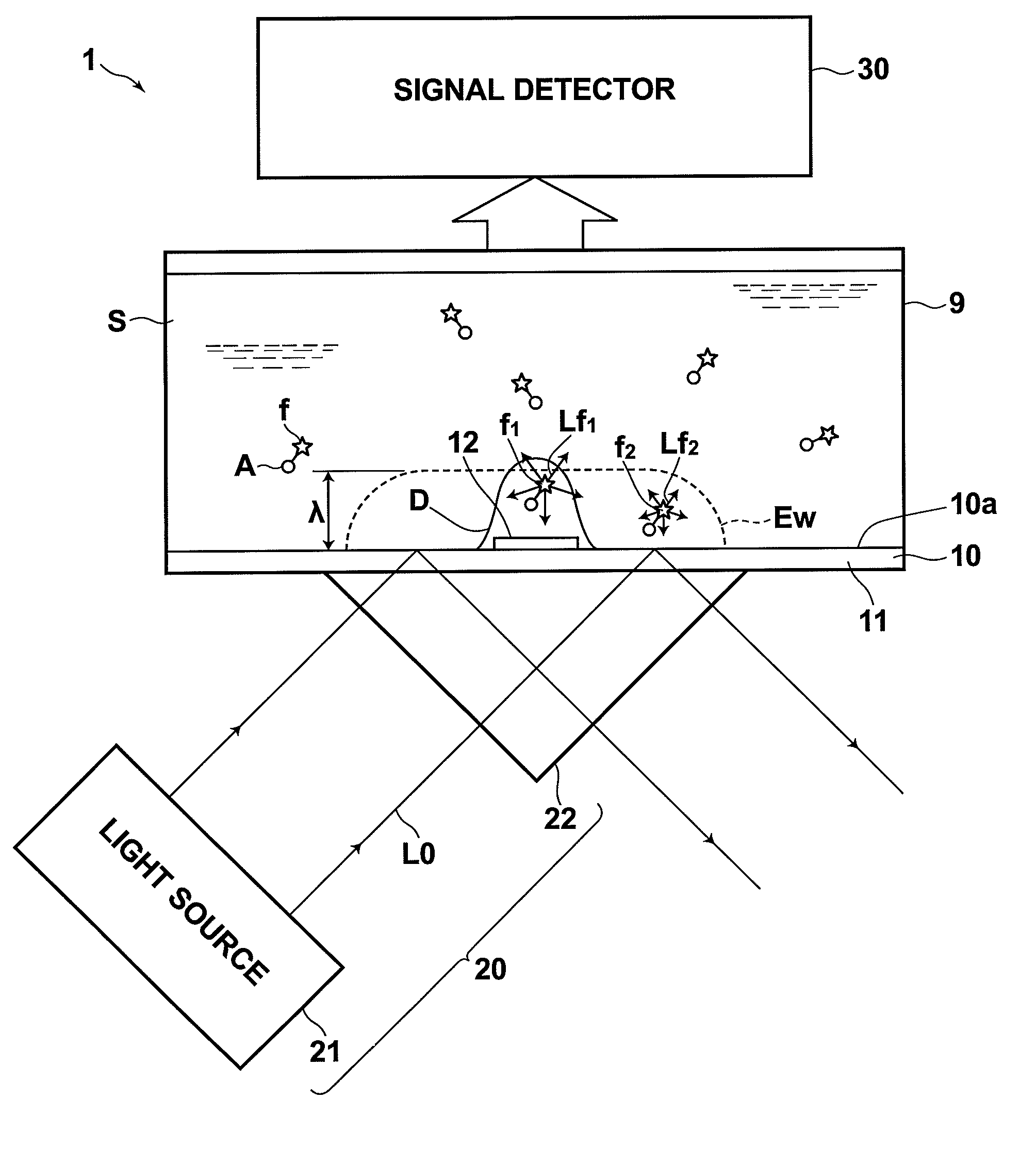
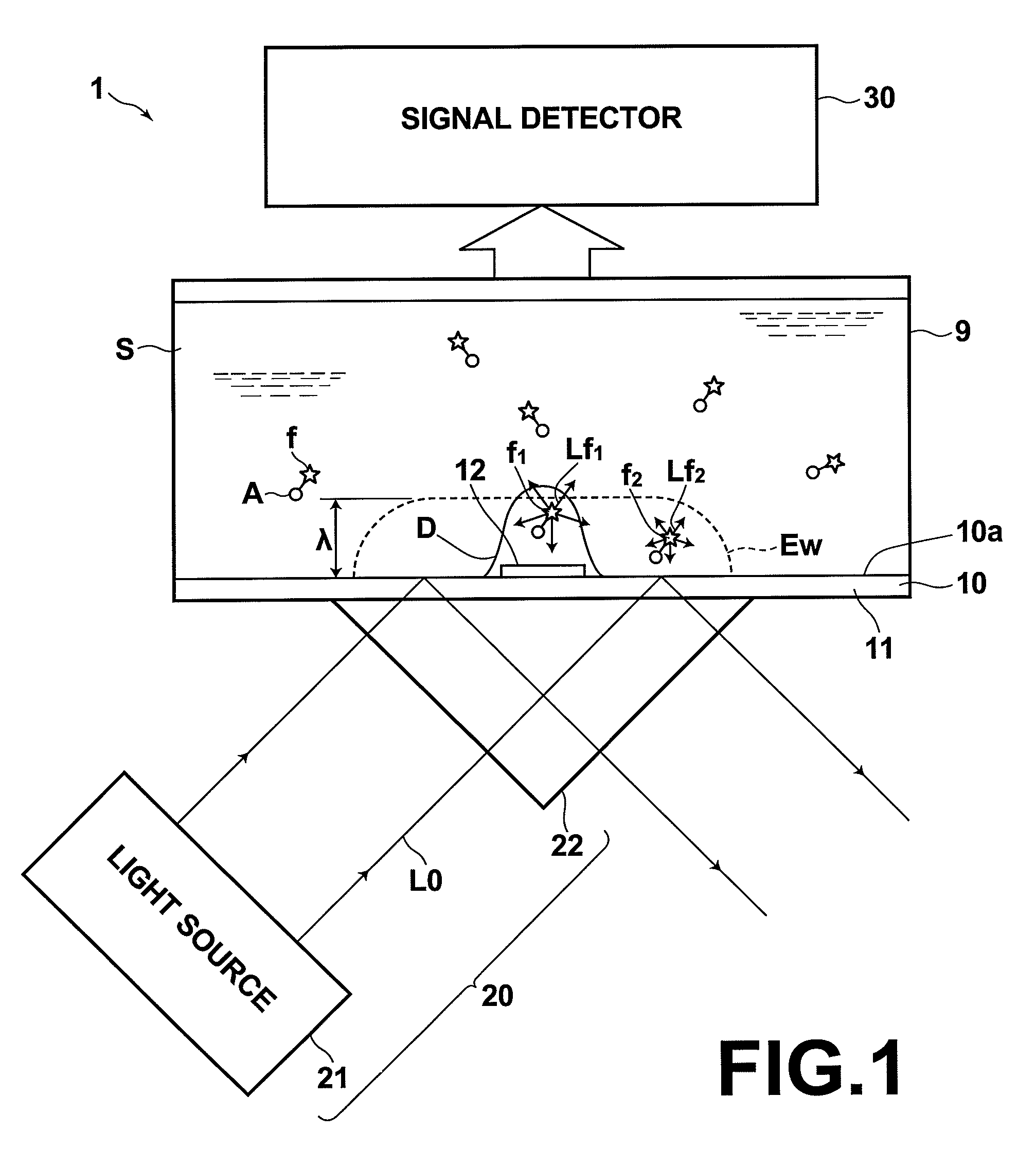
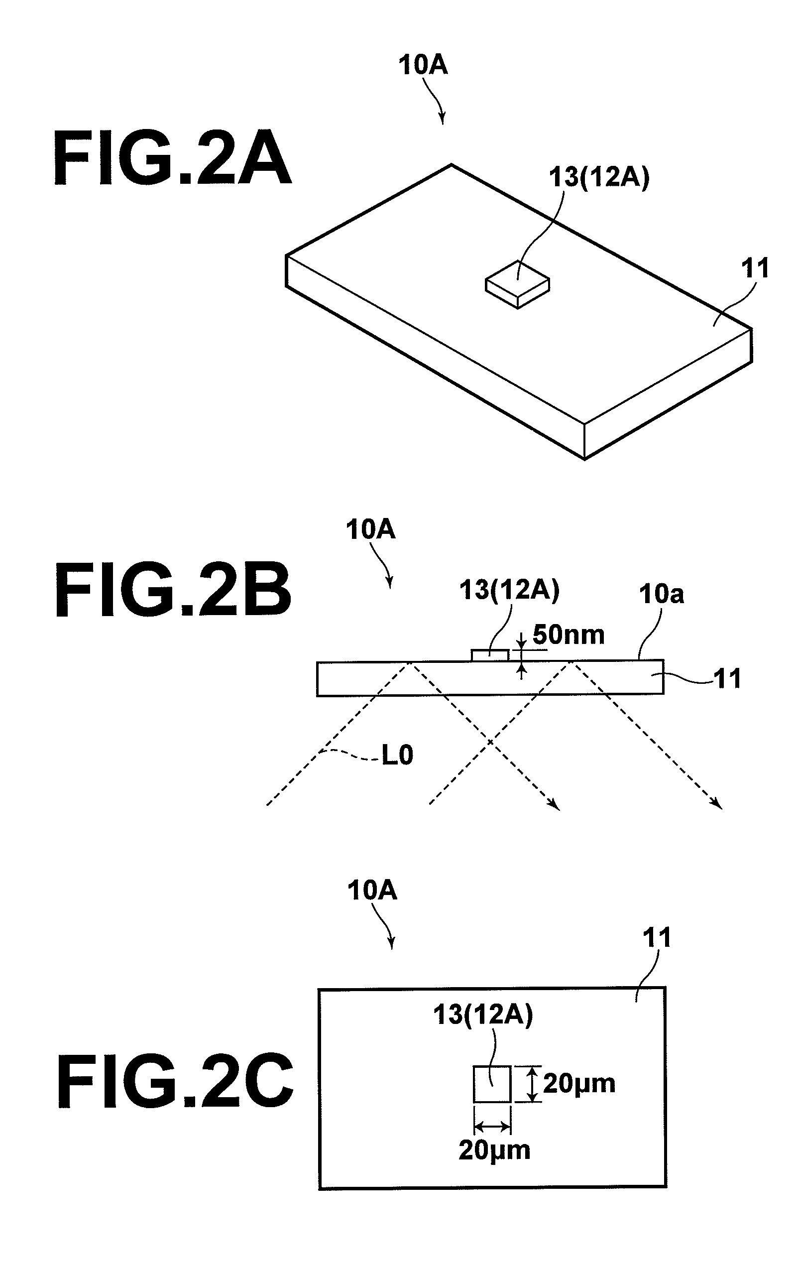
[0047]Now, a molecular fluorescence detection method, a molecular fluorescence detection apparatus for use with the method, and a sample plate according to a first embodiment of the molecular analysis light detecting method and apparatus of the invention will be described with reference to the drawings. FIG. 1 is an overall view of the apparatus, and FIGS. 2A-5B show preferred examples of the sample plate. For convenience of explanation, dimensions of components shown in the drawings are not to actual scale.

[0048]A molecular fluorescence detection apparatus 1 shown in FIG. 1 includes a sample plate 10, an excitation-light applying optical system 20 and a signal detector unit 30. The sample plate 10 includes an enhancing member 12 provided at a small predetermined area of a sample contact surface 10a, which contacts a sample S containing a substance A to be analyzed being labeled with a fluorescent label f. When the excitation light is applied, the enhancing member 12 enhances light ...

second embodiment

[0080]Now, a molecular fluorescence detection method, a molecular fluorescence detection apparatus for use with the method, and a sample plate according to a second embodiment of the invention are described. FIG. 6 is an overall view of the apparatus, and FIGS. 7A-8 show preferred examples of the sample plate in this embodiment. For convenience of explanation, dimensions of components shown in the drawings are not to actual scale. Further, components that are the same as the components in the first embodiment are designated by the same reference symbols.

[0081]A molecular fluorescence detection apparatus 2 shown in FIG. 6 includes an enhancing member 72 and an excitation-light applying optical system 20′, which are different from the corresponding components in the molecular fluorescence detection apparatus 1 of the first embodiment.

[0082]When the enhancing member 72 is illuminated by the excitation light, the enhancing member 72 generates so-called localized plasmon. Similarly to th...

third embodiment

Modifications to Third Embodiment

[0117]FIGS. 12 and 13 illustrate modifications to the third embodiment. Small metal structures 73 serving as enhancing members are formed at the small predetermined areas on the sample contact surface 10a corresponding to the first measurement area 57 and the second measurement area 58. As described above in the second embodiment, provision of the small metal structure 73 as the enhancing member allows use of incident light or transmitted light as the excitation light, in stead of the totally reflected light. In this case, the fluorescence is excited not by the evanescent light but by the excitation light L0 itself.

[0118]In an apparatus 3′ shown in FIG. 12, the excitation-light applying optical system 20 applies the excitation light L0 as transmitted light, not as totally reflected light, to the measurement area from below.

[0119]In an apparatus 3″ shown in FIG. 13, the excitation-light applying optical system 20 is disposed above the sample cell 50, ...


PUM


Abstract

A molecular analysis light detection apparatus is formed by: a sample plate provided with an enhancing member which is disposed at a small predetermined area of a sample contact surface contacting with a sample containing a substance to be analyzed and which generates an enhancing field for enhancing light generated from the substance to be analyzed at the predetermined area relative to the light at other areas of the sample contact surface when predetermined excitation light is applied; an excitation-light applying optical system for applying the excitation light to an illumination area which contains the predetermined area of the sample contact surface provided with the enhancing member and which is larger than the predetermined area; and a signal detector unit for detecting fluctuation of the light, which is enhanced by the enhancing field, generated from the substance to be analyzed.

Description

BACKGROUND OF THE INVENTION[0001]1. Field of the Invention[0002]The present invention relates to a molecular analysis light detection method, such as a molecular fluorescence detection method such as fluorescence correlation spectroscopy or fluorescence intensity distribution analysis for detecting behavior of a substance to be analyzed labeled with a fluorescent label contained in a sample, or Raman spectroscopy for spectroscopically analyzing Raman scattering light from a substance to be analyzed. The present invention also relates to a molecular analysis light detection apparatus for use with the method, and a sample plate.[0003]2. Description of the Related Art[0004]Conventionally, apparatuses for detecting the number and / or mobility of particles or molecules that emit fluorescence by receiving fluorescent signals from a small area and statistically processing the signals have been proposed and used in practice, such as Fluorescence Correlation Spectroscopy (or FCS, see “Fluores...

Claims


Application Information

Patent Timeline
Patent Type & Authority Patents(United States)
IPC IPC(8): G01J3/30
CPCG01N21/6428G01N21/648G01N21/658
Inventor KIMURA, TOSHIHITO
Owner FUJIFILM CORP
Learn More