
Convex shell for push-up handle

a push-up handle and convex shell technology, applied in the field of unstable push-up handles, can solve the problem of little effective rotational friction between the grip and the floor surface, and achieve the effect of convenient transportation, handling, and storag

Inactive Publication Date: 2012-01-31
VAYNTRAUB VLADIMIR
View PDF19 Cites 37 Cited by
  • Summary
  • Abstract
  • Description
  • Claims
  • Application Information

AI Technical Summary

Benefits of technology

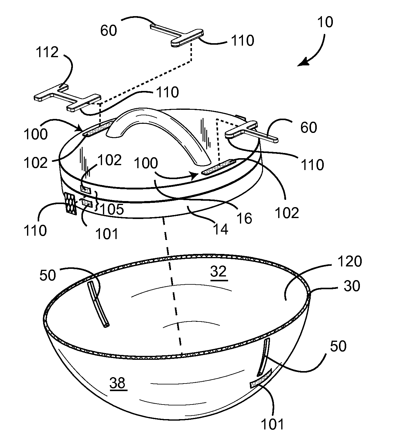
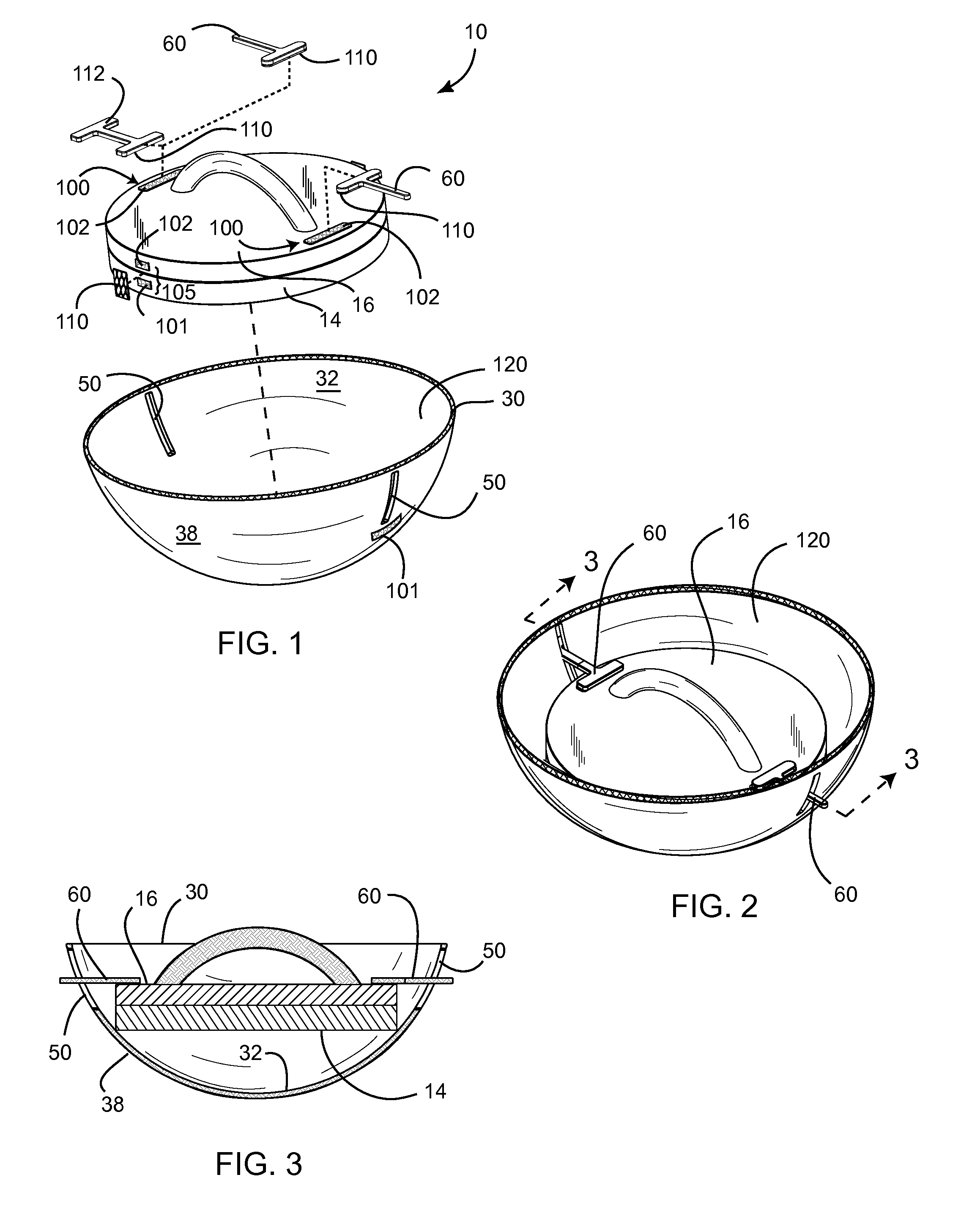
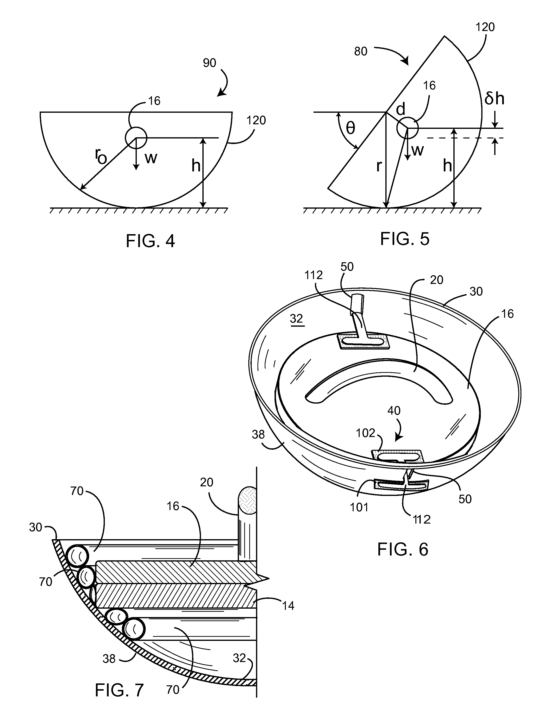
[0012]In perhaps the simplest form, the grip may be selectively and temporarily fixed to the base with a two-part hook-and-loop type fastening strip. In such an embodiment, a first piece of one part of the fastening strip is fixed with the base, and a second piece of the one part is fixed with the grip, such that a second part of the fastening strip may be fixed across each piece to mutually and selectively secure the base rotationally to the grip. As such, with the push-up handle resting in the shell, and with the convex outer surface of the shell resting on a floor surface, a user may perform push-ups such that the grip imparts rotation to the shell through the contact of the base with the shell. As the shell is substantially rigid, the outer surface contacts the floor surface at essentially a single point, resulting in little effective rotational friction between the grip and the floor surface. The shell tends to maintain a stable position on the floor, resisting tipping.

Problems solved by technology

As the shell is substantially rigid, the outer surface contacts the floor surface at essentially a single point, resulting in little effective rotational friction between the grip and the floor surface.

Method used


Image

  • Convex shell for push-up handle
  • Convex shell for push-up handle
  • Convex shell for push-up handle

Examples


Embodiment Construction

[0021]Illustrative embodiments of the invention are described below. The following explanation provides specific details for a thorough understanding of and enabling description for these embodiments. One skilled in the art will understand that the invention may be practiced without such details. In other instances, well-known structures and functions have not been shown or described in detail to avoid unnecessarily obscuring the description of the embodiments.

[0022]Unless the context clearly requires otherwise, throughout the description and the claims, the words “comprise,”“comprising,” and the like are to be construed in an inclusive sense as opposed to an exclusive or exhaustive sense; that is to say, in the sense of “including, but not limited to.” Words using the singular or plural number also include the plural or singular number respectively. Additionally, the words “herein,”“above,”“below” and words of similar import, when used in this application, shall refer to this appli...


PUM


Abstract

An improvement is disclosed for a push-up handle of the type having a cylindrical base rotatably fixed to a grip. The improvement comprises a shell having a convex outer surface and a concave inner surface, and a connector for selectively fixing the grip of the push-up handle to the shell. The shell is adapted to receive the push-up handle therein so that a peripheral portion of the base contacts the inner surface of the shell. As such, with the push-up handle resting in the shell, and with the outer surface of the shell resting on a floor surface, a user may perform push-ups such that the grip imparts rotation to the shell through the contact of the base with the shell. The outer surface contacts the floor surface at essentially a single point, resulting in little effective rotational friction between the grip and the floor surface. The shell tends to maintain a stable position on the floor, resisting tipping.

Description

CROSS-REFERENCE TO RELATED APPLICATIONS[0001]Not Applicable.STATEMENT REGARDING FEDERALLY SPONSORED RESEARCH AND DEVELOPMENT[0002]Not Applicable.FIELD OF THE INVENTION[0003]This invention relates to exercise devices, and more particularly to unstable push-up handles.DISCUSSION OF RELATED ART[0004]So-called “push-up handles” have become popular for assisting a user in keeping his arms properly positioned while doing “push-up” exercises on a floor surface. Typically such push-up handles provide a handle means for allowing the user to grasp the handle against the surface with his open palm, which puts considerably pressure on the user's wrist. Further, such prior art devices typically allow for the handle to rotate about a vertical axis.[0005]Examples of typical prior-art push-up handles can be found in the following patents and patent applications:[0006]Publication No.Issue DateFirst Named Inventor3,115,338Dec. 24, 1963Acs4,610,448Sep. 9, 1986Hill5,358,463Oct. 25, 1994FuentesD523,493J...

Claims


Application Information

Patent Timeline
IPC IPC(8): A63B71/00
CPCA63B23/1236A63B22/18
Inventor VAYNTRAUB, VLADIMIR
Owner VAYNTRAUB VLADIMIR
Learn More