
Boat anchoring system

a technology for anchoring systems and boats, which is applied in the field of boat anchoring systems, can solve the problems of tedious and time-consuming, conventional anchoring, and small vessels, and achieve the effect of quick and effective anchoring

Inactive Publication Date: 2012-01-31
THOMPSON LARRY C
View PDF10 Cites 11 Cited by
  • Summary
  • Abstract
  • Description
  • Claims
  • Application Information

AI Technical Summary

Benefits of technology

[0006]It is therefore an object of the present invention to provide an innovative anchoring system that allows small boats, and especially shallow water boats used for coastal, inland and back bay fishing, to be quickly and effectively anchored in place at a selected location in a body of water.
[0007]It is a further object of this invention to provide an anchoring system that eliminates the use of conventional anchors currently used with coastal, inland and back bay fishing boats and which overcomes the problems typically exhibited by such anchors.
[0008]It is a further object of this invention to provide an anchoring system that is much easier and faster to operate than standard shallow water boat anchors and which does not require arduous lifting and retrieving of a heavy and / or bulky anchor.

Problems solved by technology

Securely anchoring even a small marine vessel such as a flats boat or other shallow water vessel can be quite tedious and time consuming.
Conventional anchors, even those for small vessels, tend to be fairly heavy and can be difficult for some persons to drop and retrieve.
Such anchors are also apt to become snagged or caught in underwater vegetation and refuse.
Conventional anchor lines present additional problems during inland, coastal or back bay fishing of the type described above.
Often, a hooked fish may pull the fishing line such that it strikes one of the deployed anchor lines and breaks.
This causes both the fish and fishing tackle to be lost and requires time consuming and aggravating replacement or repair of the lost hook and tackle.
To date, however, push poles have not been used to anchor the boat for fishing or otherwise.

Method used


Image

  • Boat anchoring system
  • Boat anchoring system
  • Boat anchoring system

Examples


Embodiment Construction

[0023]Other objects, features and advantages will occur from the following description of a preferred embodiment and the accompanying drawings, in which:

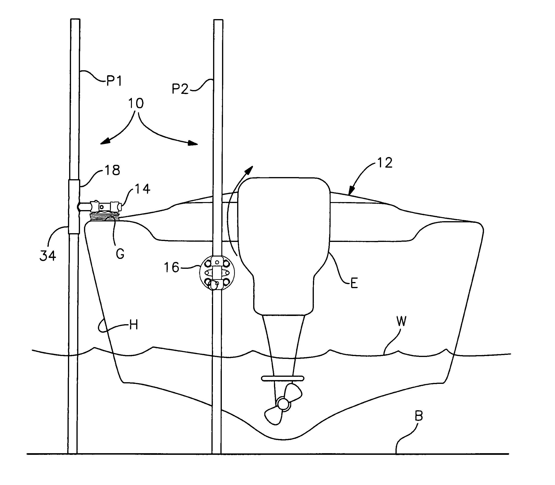
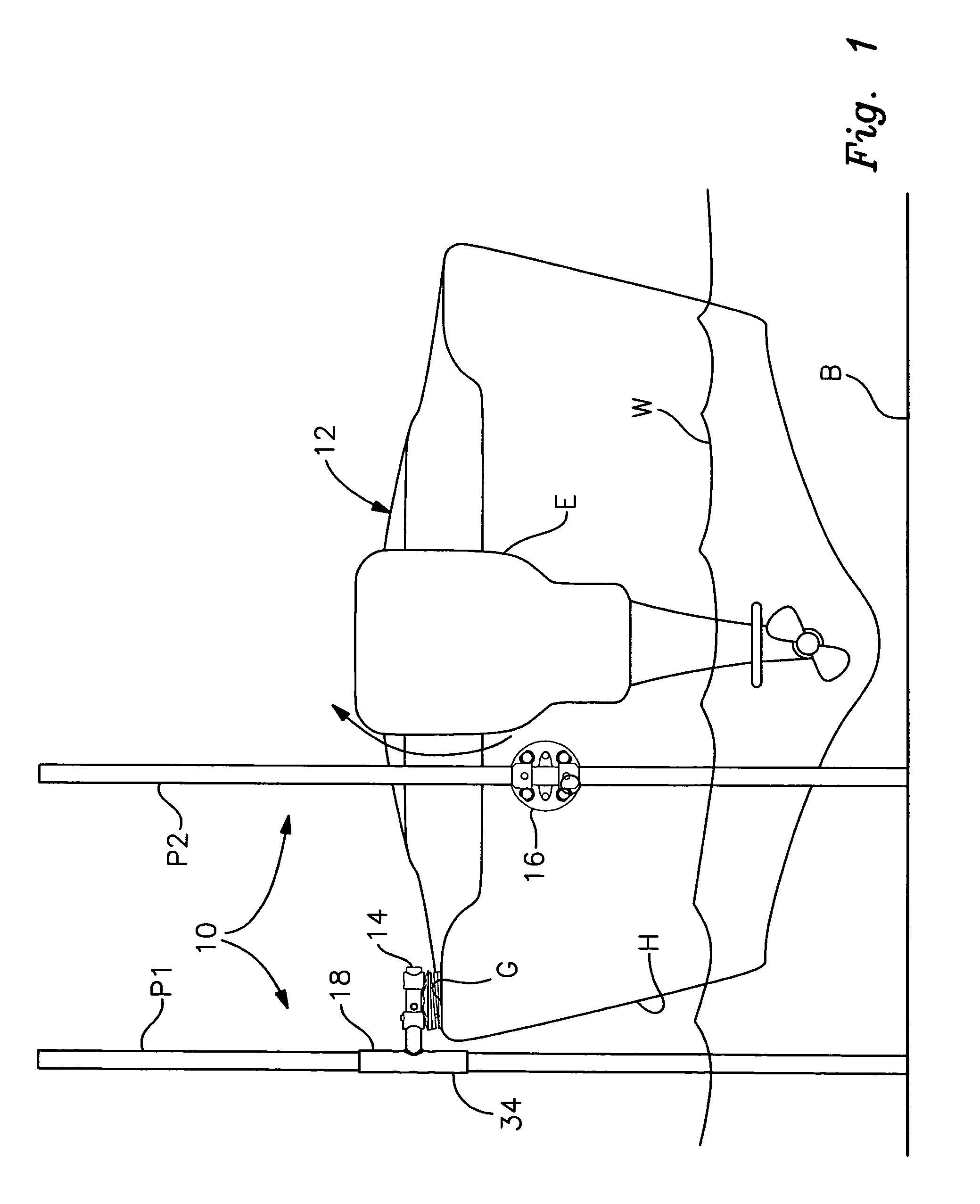
[0024]FIG. 1 is an elevational rear view of a boat equipped with the anchoring system of this invention, which anchoring system is deployed to anchor the boat to the bottom of a shallow body of water;

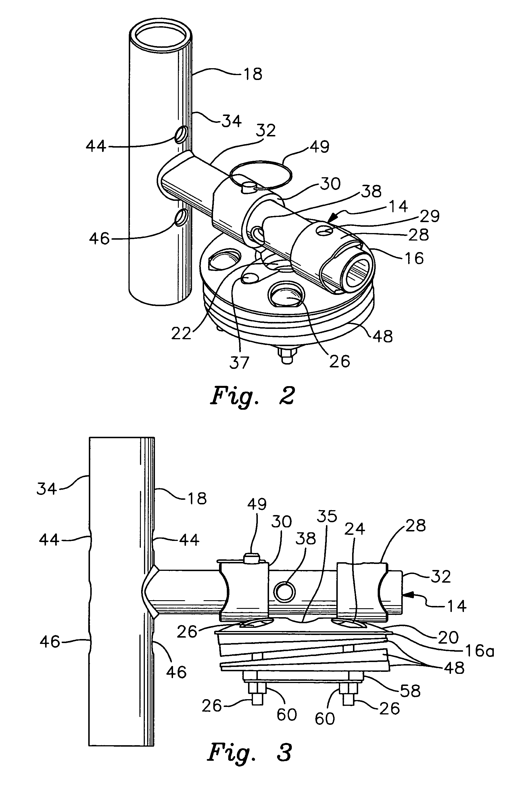
[0025]FIG. 2 is a perspective view of an adjustable anchoring apparatus used in the anchoring system; the apparatus is mounted to the gunwale, deck or other horizontal surface proximate a peripheral edge of the vessel;

[0026]FIG. 3 is a side elevational view of the apparatus of FIG. 2;

[0027]FIG. 4 is a top plan view of the apparatus of FIGS. 2 and 3;

[0028]FIG. 5A is a perspective view of the anchor fixture employed in the system of this invention;

[0029]FIG. 5B is a perspective view of the base of the anchor fixture;

[0030]FIG. 5C is a perspective view of the adjustable pole holder;

[0031]FIG. 6 is a top plan view of a representative shim t...


PUM


Abstract

An anchoring system for a boat includes a pair of anchor fixtures, each having a base and a tube carried by and extending across the base. A first of the anchor fixtures is mountable proximate the peripheral edge of the vessel with the tube oriented to extend in a generally horizontal direction. The other, second anchor fixture is mounted exteriorly to the transom of other surface of the hull such that the longitudinal axis of the tube extends generally vertically. The first anchor fixture accommodates an adjustable pole holder that has a stem for selectively engaging with the first anchor fixture to provide anchoring, transporting and stowed conditions. A sleeve is interconnected angularly to the stem for holding a first pole, which may be operated by adjusting the pole holder to engage the bottom of the body of water. A second pole is received by the tube of the second anchor fixture to likewise engage the bottom of the body of water such that the boat is anchored thereto.

Description

FIELD OF THE INVENTION[0001]This invention relates to a boat anchoring system and, more particularly, to an apparatus for use in combination with one or more elongate push poles to anchor a fishing boat or other shallow water marine vessel to the bottom of a body of water.BACKGROUND OF THE INVENTION[0002]Recreational shallow water fishing is extremely popular in a wide variety of locations including, but not limited to, lakes, bays, coastal waters, rivers and other waterways. Many types of small and modestly sized boats are used for this activity. The fisherman typically navigates the vessel to a selected destination and then anchors the boat before starting to fish.[0003]Securely anchoring even a small marine vessel such as a flats boat or other shallow water vessel can be quite tedious and time consuming. Usually, a pair of anchors must be separately deployed to effectively hold the boat in place and minimize drift. Conventional anchors, even those for small vessels, tend to be fa...

Claims


Application Information

Patent Timeline
IPC IPC(8): E02B3/24B63B17/00
CPCB63B21/22B63B21/26E02B3/24
Inventor THOMPSON, LARRY C.
Owner THOMPSON LARRY C
Learn More