Method for manufacturing a series of electric terminals

a technology of electric terminals and manufacturing methods, applied in the direction of electrical equipment, line/current collector details, coupling contact members, etc., can solve the problems of high manufacturing cost, difficult to meet the needs of customers, so as to reduce the effect of saving capital expenditures and inventory costs

Inactive Publication Date: 2012-01-31
APTIV TECH LTD
View PDF49 Cites 4 Cited by
  • Summary
  • Abstract
  • Description
  • Claims
  • Application Information

AI Technical Summary

Benefits of technology

[0007]Basically the series of electric terminals is manufactured in a two stage manufacturing process where all members of the series have an identical contact portion formed in a primary operation in a common set of progressive forming dies. Each member of the series then has their unique attachment portions formed in a secondary operation in a unique set of progressive forming dies thereby reducing capital expenditures and inventory costs.
[0008]Savings in capital expenditures and inventory costs are particularly advantageous in electric terminals that have a contact portion that is progressively formed in a relatively large number of steps in comparison to a relatively few number of steps needed to form the attachment portion. This advantage increases with the complexity of the contact portion, and can result in considerable savings, particularly in the case of female terminals that often have complex contact portions.

Problems solved by technology

However, the known method is expensive from a manufacturing standpoint because of the requirement for several sets of unique progressive forming dies and the need for a large inventory storing each of the several members of the series of electric terminals.
The expense is particularly notable when one or more member of the series has a relatively low volume of use.

Method used


Image

  • Method for manufacturing a series of electric terminals
  • Method for manufacturing a series of electric terminals
  • Method for manufacturing a series of electric terminals

Examples


Embodiment Construction

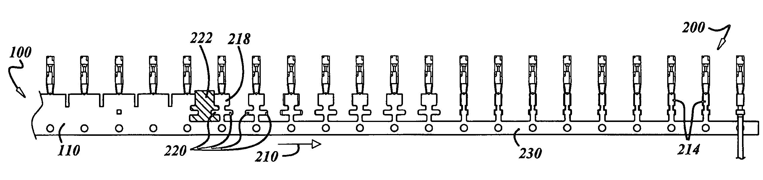
[0017]Referring now to the drawings, FIGS. 1-4 illustrate a typical female electric terminal 10 that can be manufactured by the method that is described in connection with FIGS. 5-8. Electric terminal 10 comprises a female receptacle portion 12 for receiving a male terminal (not shown) at one end and an attachment portion 14 at an opposite end for attaching terminal 10 to an electric cable 16. Forming the attachment portion typically takes less than 10 steps.

[0018]Electric terminals such as the female electric terminal 10 are conventionally formed from a strip of metal is a series of dies that punch and form the strip in several steps usually on the order of 30-40 steps. Because of the need for a receptacle as well as a resilient contact tongue within the receptacle, the female receptacle portion 12 is much more complicated structurally than attachment portion 14 which typically merely comprises core wings 18 and insulation crimp wings 20 which are formed in barrels. The core and in...


PUM

PropertyMeasurementUnit
sizeaaaaaaaaaa
sizeaaaaaaaaaa
sizeaaaaaaaaaa

Abstract

A series of electric terminals in which each member of the series has an identical receptacle portion at one end and a unique cable attachment portion at an opposite end is manufactured by forming a generic strip of partially formed terminals having a receptacle portion at one end in a first progressive die forming operation for all members of the series of electric terminals. Strips of completely formed electric terminals of particular members of the series of electric terminals are then completed in respective unique die progressive die forming operations using the generic strip of partially formed terminals. A modular die may be used for forming the strips of completely formed electric terminals from the intermediate generic the strip of partially formed terminals.

Description

BACKGROUND OF THE INVENTION[0001]This invention relates generally to a method of manufacturing a series of electric terminals.[0002]Electric terminals generally comprise a contact portion at one end and an attachment portion at an opposite end. The contact portion is adapted for a temporary connection to a mating contact portion of another electric terminal while the attachment portion is adapted for permanent attachment to another electric element such as an electric cable or the like.[0003]Thus a series of electric terminals may have identical contact portions at one end while having different attachment portions at an opposite end that are adapted for permanent attachment to different electric elements such as several different electric cables of various sizes and / or types.[0004]In the past each member in a series of electric terminals for electric cables was manufactured with an identical contact portion at one end and a unique attachment portion at the other end for permanent a...

Claims


Application Information

Patent Timeline
Patent Type & Authority Patents(United States)
IPC IPC(8): H01R43/16
CPCH01R43/16H01R4/185H01R13/11Y10T29/49204Y10T29/49002Y10T29/49117
Inventor HEACOX, MARK J.SHEMITZ, SCOTTXU, XUEFUBECK, DAVID A.
Owner APTIV TECH LTD
Why Eureka
Try Eureka