
Fast characterization of fluid dynamics

a fluid dynamics and fast technology, applied in image data processing, analogue and hybrid computing, complex mathematical operations, etc., can solve the problems of inability to realize real-time computer graphics applications, high computational complexity of fluid simulations, and high cost of accuracy, so as to achieve fast computation of fluid velocity fields

Inactive Publication Date: 2012-01-17
EXOCORTEX TECH
View PDF44 Cites 19 Cited by
  • Summary
  • Abstract
  • Description
  • Claims
  • Application Information

AI Technical Summary

Benefits of technology

"The present invention provides methods and apparatus for fast computation of fluid velocity fields in real-time applications. The invention allows for the determination and display of fluid flow in a bounded space with the use of reference velocity fields. The invention also allows for the evaluation of velocity perturbation caused by placing an object at a specific position within the bounded space. The invention uses a set of reference velocity fields, oriented in specified directions, to determine the velocity fields at different sampling points in the space. The velocity fields can be determined for predefined speed values or interpolated from the reference fields for real-time use. The invention also provides a method for approximating the perturbation vectors caused by the object's movement. Overall, the invention allows for the efficient computation of fluid velocity fields in real-time applications."

Problems solved by technology

Fluid simulations are very computationally extensive and thus have so far proved to be impractical for real-time computer graphics applications.
The speed comes at the cost of accuracy, generality, and increased memory requirements.
Such a requirement makes it impossible to implement the method of Treuille et al. in a video game engine such as an XBOX or Sony's PS3 (PlayStation 3).

Method used


Image

  • Fast characterization of fluid dynamics
  • Fast characterization of fluid dynamics
  • Fast characterization of fluid dynamics

Examples


Embodiment Construction

Terminology

Fluid: The term is used herein to refer to any gas or liquid.

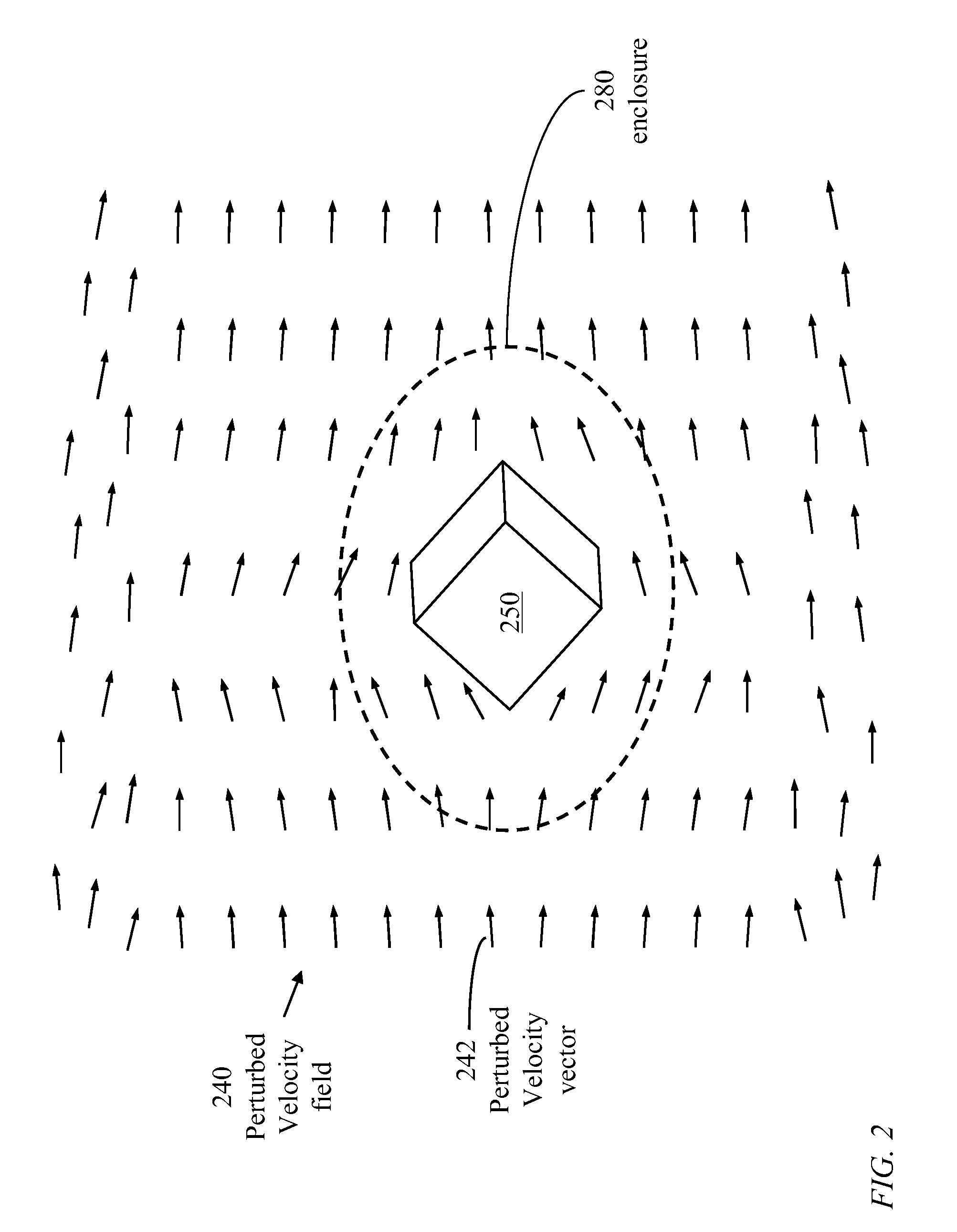
Object: The term object refers to a solid material or structure placed in a space sustaining fluid flow.

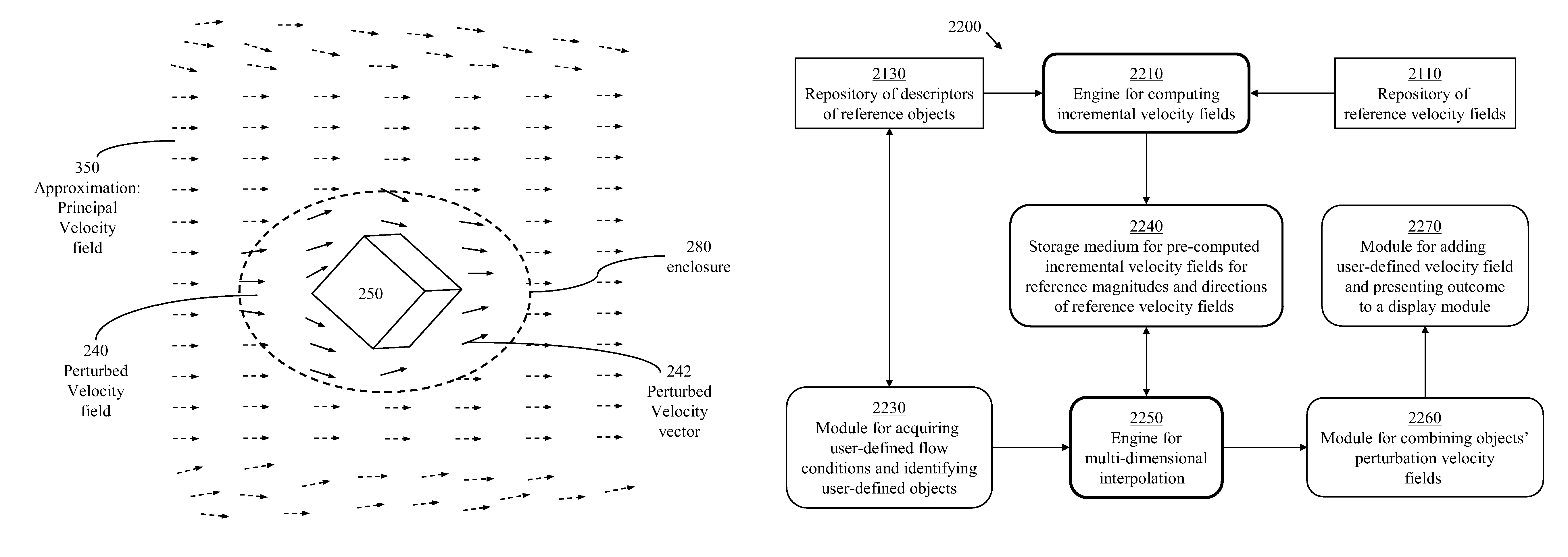
Velocity field: The term is used herein to refer to a vector field within a medium containing fluid where a vector at a specific point within the medium represents the velocity of a particle at the specific point.

Velocity vector: A velocity vector represents a velocity field at a specific point.

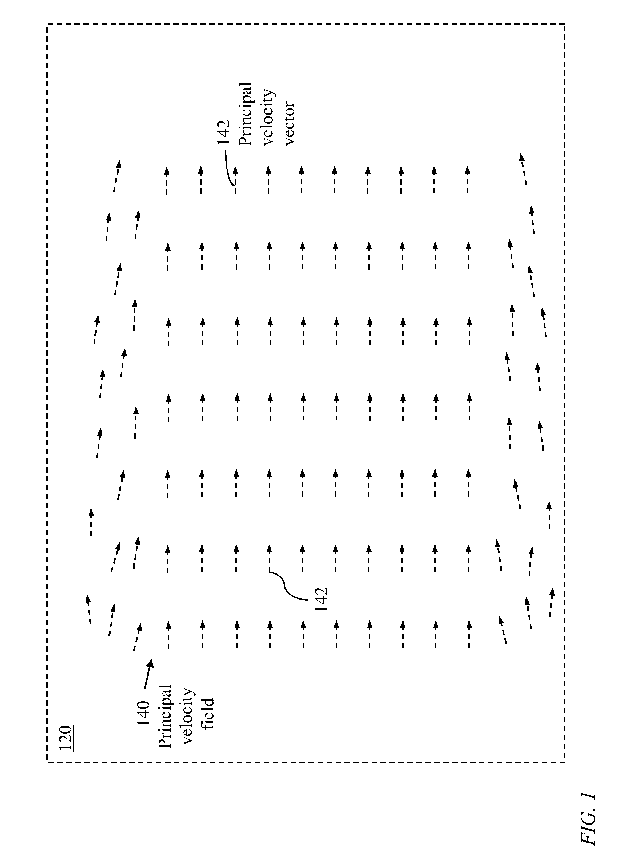
Principal velocity field: A principal velocity field, also called a background velocity field, is used herein to denote a velocity field induced within a bounded space of static boundary.

Principal velocity vector: A principal velocity vector, also called a background velocity vector, represents the velocity of a particle at a specific position within the bounded space.

Reference velocity fields: A reference velocity field is a principal velocity field of a predefined direction. The mutually orthogonal axes in a Cartesian...


PUM


Abstract

Methods and apparatus for fast computation of fluid velocity fields in the presence of objects causing flow discontinuity are disclosed. Rigorous evaluation of perturbed velocity fields, each resulting from placing an object in a bounded space sustaining a reference velocity field, are determined for different orientations of the object with respect to a reference velocity field and different values of the magnitude of the velocity field. A velocity field is determined at selected sampling points within an enclosure surrounding the object. Pre-computed perturbed velocity fields determined for each object of a set of reference objects are stored in a computer memory. Fast real-time computation of velocity-field perturbations caused by presence of objects at arbitrary positions in a space sustaining velocity fields of different magnitudes and directions are realized using the stored pre-computed data.

Description

CROSS REFERENCE TO RELATED APPLICATIONS[0001]The present application claims the benefit of U.S. provisional application Ser. No. 61 / 009,440 filed Dec. 31, 2007 to Houston et al., entitled “Methods of Modelling Fluid Flow”, the contents of which are incorporated herein by reference.FIELD OF THE INVENTION[0002]The present invention relates to characterization of fluid dynamics in a partially bounded space subjected to a forced fluid stream.BACKGROUND OF THE INVENTION[0003]Real-time fluid modeling in video games, training and interactive media is an area of great interest. One important part of fluid modeling involves providing a real-time fluid system for computer graphics applications to model air flow, dust, leaves, texture sprites, volumetric smoke densities, magical effects and explosions, for example. Fluid simulations are very computationally extensive and thus have so far proved to be impractical for real-time computer graphics applications.[0004]Modern online simulations used ...

Claims


Application Information

Patent Timeline
Patent Type & Authority Patents(United States)
IPC IPC(8): G06G7/50G06F17/17G06T17/00G01M9/00G06T15/10
CPCG01P5/001G06T17/00
Inventor HOUSTON, BENJAMIN BARRIE
Owner EXOCORTEX TECH
Learn More