
Quantum cascade laser element

a quantum cascade and laser element technology, applied in the direction of laser optical resonator construction, laser details, optical resonator shape and construction, etc., can solve the problems of deteriorating laser element temperature characteristics, reducing yield and reproducibility, and unable to reliably cw-oscillation a single-mode light at room temperature or a temperature in proximity, so as to suppress the deterioration of laser element temperature characteristics and the decline of yield and reproducibility, the effect o

Active Publication Date: 2012-01-17
HAMAMATSU PHOTONICS KK
View PDF5 Cites 1 Cited by
  • Summary
  • Abstract
  • Description
  • Claims
  • Application Information

AI Technical Summary

Benefits of technology

This configuration allows for reliable CW oscillation of single-mode light at room temperature or proximity temperatures, improving temperature characteristics and yield / reproducibility compared to buried-grating approaches.

Problems solved by technology

H10-321951 has a problem that, since this is aimed at an operation at an extremely low temperature, it is absolutely impossible to CW-oscillate a single-mode light at room temperature or a temperature in proximity thereof according to the conditions described in Patent Document 1.
Moreover, the buried-grating type quantum cascade laser element has a problem that not only do temperature characteristics of the laser element deteriorate but the yield and reproducibility also decline.
And, when the thickness of the cladding layer located between the active layer and diffraction grating exceeds 42+10% of the wavelength of oscillating light (hereinafter, referred to as an “oscillation wavelength”), light seeping from the active layer to the diffraction grating is weakened and it thus becomes difficult to realize a DFB operation.
On the other hand, when the thickness of the cladding layer located between the active layer and diffraction grating falls below 42−10% of the oscillation wavelength, light leakage is increased and it thus becomes difficult to realize CW oscillation at room temperature or a temperature in proximity thereof.

Method used


Image

  • Quantum cascade laser element
  • Quantum cascade laser element
  • Quantum cascade laser element

Examples


Embodiment Construction

[0025]Hereinafter, preferred embodiments of the present invention will be described in detail with reference to the drawings. Also, the same or corresponding parts are denoted with the same reference numerals in each figure, and overlapping description will thus be omitted.

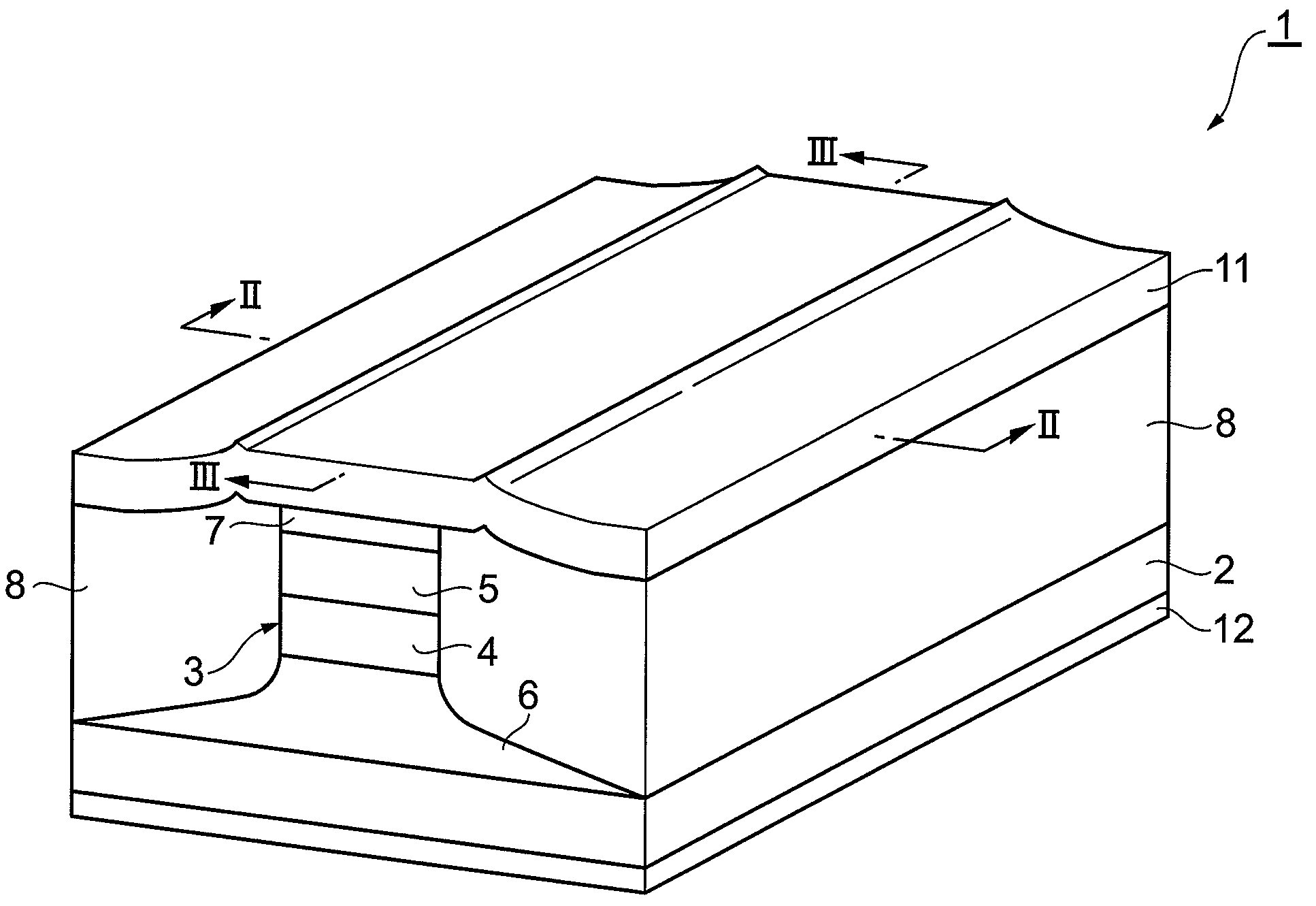
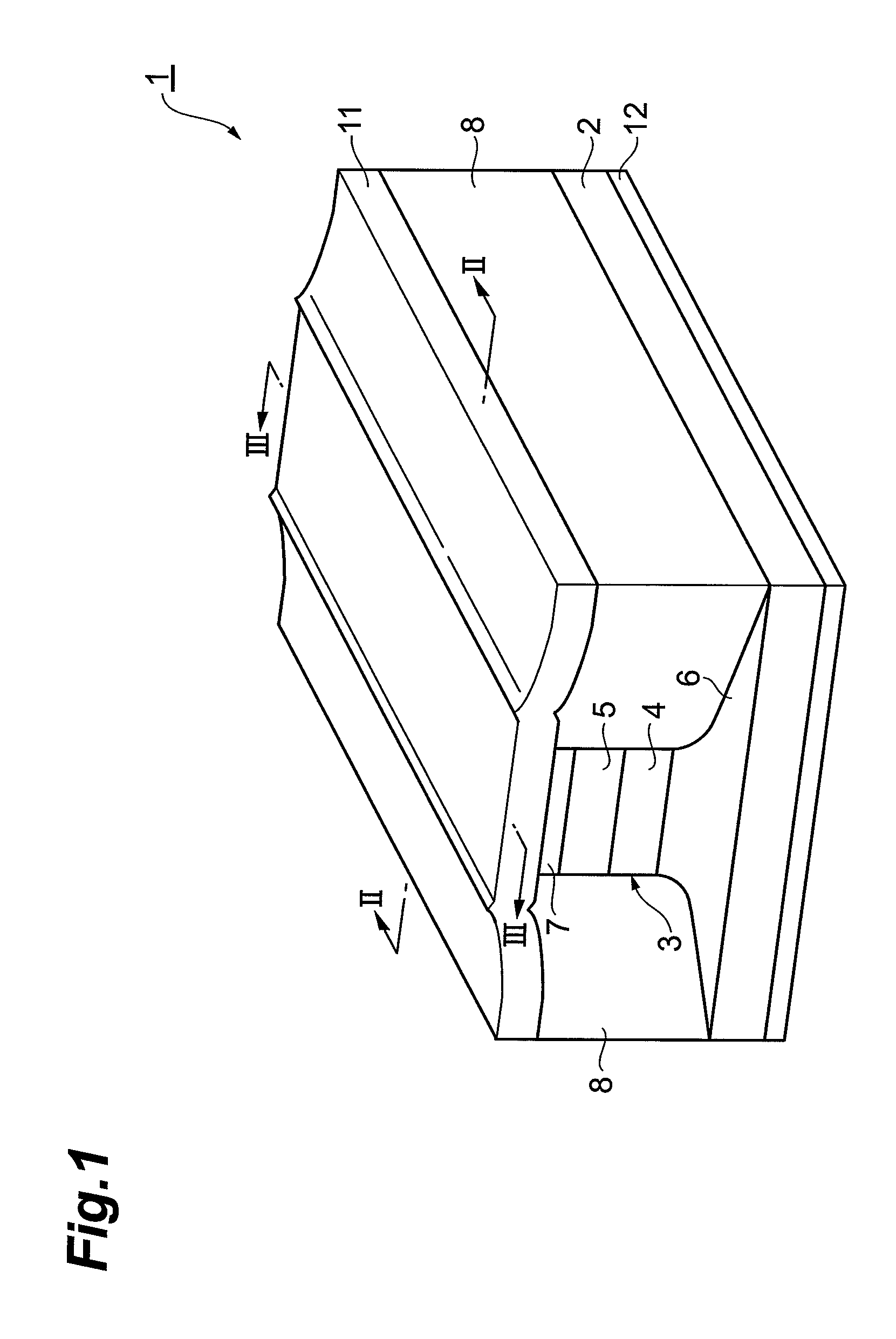
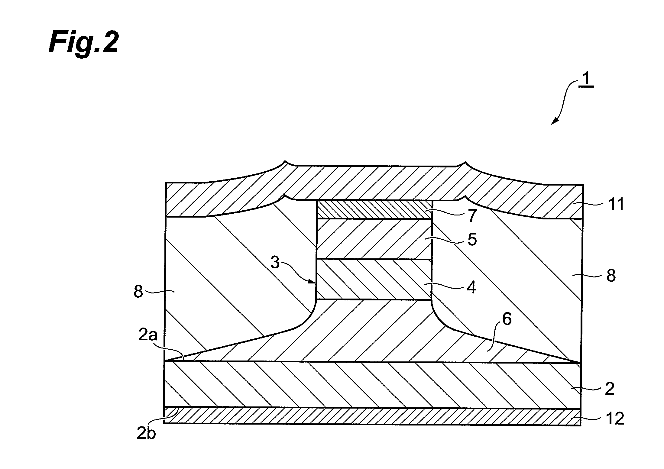
[0026]FIG. 1 is a perspective view of an embodiment of a quantum cascade laser element according to the present invention, FIG. 2 is a sectional view along a line II-II of FIG. 1, and FIG. 3 is a sectional view along a line III-III of FIG. 1. A quantum cascade laser element 1 is a DFB element that oscillates a single-mode light, and formed in an almost rectangular parallelepiped shape. On one major surface 2a of a substrate 2 having a rectangular thin plate shape, a laminate 3 having a stripe structure is formed. The laminate 3 is formed, with the longitudinal direction of the quantum cascade laser element 1 set as a stripe direction (resonance direction of light), so that a section orthogonal to the stripe direct...


PUM


Abstract

A DFB quantum cascade laser element that can reliably CW-oscillate a single-mode light even at room temperature or a temperature in proximity thereof is provided. In a quantum cascade laser element 1, a top-grating approach for which a diffraction grating 7 is formed on a laminate 3 is adopted, and thus in comparison with a buried-grating approach, deterioration in temperature characteristics of the laser element and decline in the yield and reproducibility are suppressed. In addition, since the thickness of a cladding layer 5 located between an active layer 4 and the diffraction grating 7 is within a range of 42±10% of the oscillation wavelength, weakening of light seeping from the active layer 4 to the diffraction grating 7 or an increase in light leakage is prevented. Consequently, by the quantum cascade laser element 1, a single-mode light can be reliably CW-oscillated even at room temperature or a temperature in proximity thereof.

Description

BACKGROUND OF THE INVENTION[0001]1. Field of the Invention[0002]The present invention relates to a distributed feedback quantum cascade laser element that oscillates a single-mode light.[0003]2. Related Background Art[0004]The quantum cascade laser element is a monopolar type element that includes a laminate including an active layer formed by laminating emitting layers and injection layers alternately and can generate, in the active layer, light by electron transition between subbands in a quantum well structure. Quantum cascade laser elements are capable of realizing a high-efficiency and high-output operation by using alternately cascade-connected emitting layers and injection layers as active layers, and thus have received attention as sophisticated semiconductor light sources covering the mid-infrared region to the teraheltz (THz) region.[0005]In the quantum cascade laser element, when voltage is applied to the laminate, electrons transit from an upper level to a lower level in...

Claims


Application Information

Patent Timeline
Patent Type & Authority Patents(United States)
IPC IPC(8): H01S5/00H01S3/08H01S5/12
CPCB82Y20/00H01S5/12H01S3/08031H01S5/0655H01S5/2272H01S5/3412H01S5/34366
Inventor SUGIYAMA, ATSUSHIOCHIAI, TAKAHIDEFUJITA, KAZUUEAKIKUSA, NAOTAEDAMURA, TADATAKAFURUTA, SHINICHI
Owner HAMAMATSU PHOTONICS KK
Learn More