
Variable shear line lock cylinder

a lock cylinder and variable shear technology, applied in the direction of cylinder locks, building locks, construction, etc., can solve the problems of unfavorable door handle rotation, lock cylinder will no longer permit the rotation of the door handle assembly, and the first and second shear zones of the respective pin assemblies are not properly aligned

Inactive Publication Date: 2012-01-17
SPECTRUM BRANDS INC
View PDF41 Cites 4 Cited by
  • Summary
  • Abstract
  • Description
  • Claims
  • Application Information

AI Technical Summary

Benefits of technology

Enables re-keying without disassembly, simplifying the process and reducing production costs by using a single key to align shear zones, allowing for efficient reconfiguration of pin positions within existing components.

Problems solved by technology

In this regard, a lost or stolen key may provide unwanted operation of the lock cylinder and unwanted access through the door.
Once the new pins are installed, the lock cylinder will no longer permit rotation of the door handle assembly if the old key is used in the lock cylinder.
As can be appreciated, the old key is not commensurate with the new pin heights and therefore will not properly align the first and second shear zones of the respective pin assemblies.
While conventional lock cylinders adequately provide for a re-keying operation of a lock cylinder, they suffer from the disadvantage of requiring partial disassembly of the lock cylinder and typically require a specialized technician, such as a locksmith, to perform the re-keying operation.
Further, conventional lock cylinders suffer from the disadvantage of requiring various pin heights and combinations thereof to properly re-key the cylinder.
Further yet, conventional re-keying kits require door hardware manufacturers to produce varying pin heights for each kit, thereby overproducing the required number of individual pins to simply re-key one lock cylinder.

Method used


Image

  • Variable shear line lock cylinder
  • Variable shear line lock cylinder
  • Variable shear line lock cylinder

Examples


Embodiment Construction

[0022]The following description of the preferred embodiment(s) is merely exemplary in nature and is in no way intended to limit the invention, its application, or uses.

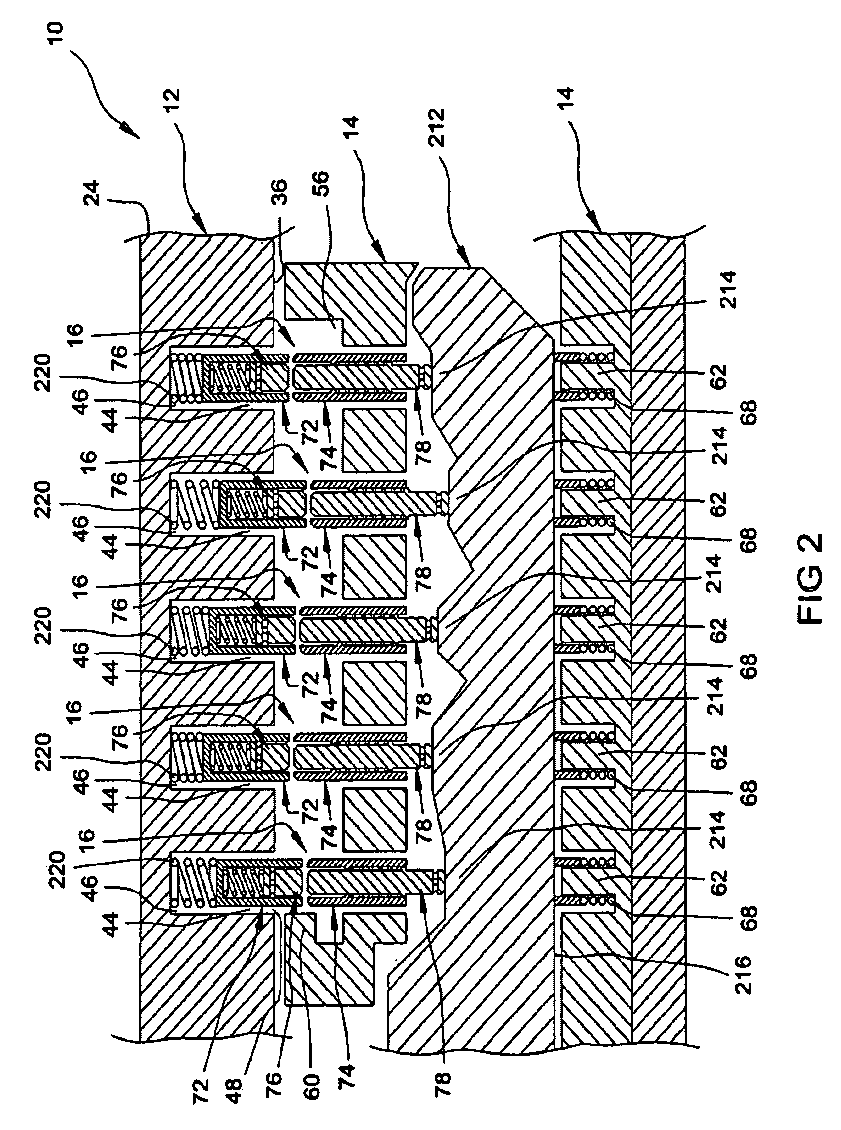
[0023]With reference to the figures, a variable shear line lock cylinder 10 is provided and includes an outer cylinder 12, an inner cylinder 14, a plurality of pin assemblies 16, a lock assembly 18, and actuation mechanism 20. The outer cylinder 12 rotatably receives the inner cylinder 14 while the pin assemblies 16 are disposed therebetween. The pin assemblies 16 are operable to selectively prevent rotation of the inner cylinder 14 relative to the outer cylinder 12 and are positionable relative to the inner and outer cylinders 14, 12 through engagement with the lock assembly 18. In addition, the actuation mechanism 20 interacts with the pin assemblies 16 and is operable to allow rotation of the inner cylinder 14 relative to the outer cylinder 12, as will be discussed further below.

[0024]The outer cylinder 12 includes...


PUM


Abstract

A lock cylinder is provided and includes an outer cylinder having a bore, an inner cylinder rotatably disposed within the bore, and a pin assembly disposed within the inner and outer cylinders. The pin assembly is operable to selectively lock the inner cylinder relative to the outer cylinder. The pin assembly includes an upper shear cylinder positionable relative to the outer cylinder and a lower shear cylinder positionable relative to the inner cylinder. The upper and lower shear cylinders are movable to define a first shear line therebetween. In addition, the pin assembly includes an upper pin slidable within the upper shear cylinder and a lower pin slidable within the lower shear cylinder, whereby the upper and lower pins define a second shear line therebetween. The lock cylinder is positionable from a locked position to an unlocked position when the first shear line is aligned with the second shear line.

Description

FIELD OF THE INVENTION[0001]The present application is a divisional application of Application Ser. No. 10 / 815,279 for VARIABLE SHEAR LINE LOCK CYLINDER filed Apr. 1, 2004 by Alston E. Williams, now U.S. Pat. No. 7,162,901.BACKGROUND OF THE INVENTION[0002]It is well known in the art to provide a door hardware assembly that is operable to maintain a door in a closed position by selectively securing the door to a doorframe. It is equally well known to provide a door hardware assembly that is capable of being locked to selectively prevent operation of the door hardware assembly. As can be appreciated, by preventing operation of the door hardware assembly, the door will remain closed and in a locked condition. Such conventional door hardware assemblies generally include a handle assembly, lock cylinder, and key, whereby the key is operable to selectively lock the lock cylinder to prevent operation of the door handle assembly and maintain the door in the closed and locked condition.[0003...

Claims


Application Information

Patent Timeline
Patent Type & Authority Patents(United States)
IPC IPC(8): E05B27/04E05B27/00
CPCE05B27/00E05B27/005E05B27/0021Y10T70/774Y10T70/7605Y10T70/7734Y10T70/7565
Inventor WILLIAMS, ALSTON E.
Owner SPECTRUM BRANDS INC
Learn More