
Aircraft steering angle warning system

a technology of steering angle and warning system, which is applied in the direction of wheel mounting apparatus, vehicle position/course/altitude control, underwater vessels, etc., can solve the problems of system ineffectiveness, damage to the nose landing gear assembly, and the steering angle may be too large, etc., to achieve simple, reliable and/or effective

Active Publication Date: 2012-01-10
AIRBUS OPERATIONS LTD
View PDF19 Cites 13 Cited by
  • Summary
  • Abstract
  • Description
  • Claims
  • Application Information

AI Technical Summary

Benefits of technology

[0006]The present invention seeks to mitigate at least one of the above-mentioned disadvantages. The present invention alternatively or additionally seeks to provide a simple, reliable and / or effective means for providing a warning of excessive steering angle during an aircraft ground manoeuvre.
[0013]An arrangement in which an element of the steering angle warning system is part of, or is integrated with, another system on the aircraft is particularly advantageous since this enables the warning system to be relatively simple and for example may require relatively little modification of an existing aircraft when retrofitting the steering angle warning system, and / or may require relatively little modification of future aircraft design. In addition, existing aircraft systems are typically very reliable, having passed stringent safety tests.
[0022]The alarm unit may also be arranged to generate the alarm if, and preferably only if, certain other parameters (other than the steering angle being greater than a particular value) are met. The other parameters may include a user input. For example, the alarm unit may be arranged to generate the alarm only if the tow key is engaged. This may prevent the alarm being generated accidentally, when the aircraft is not being towed. The alarm unit may be arranged to generate the alarm for a short period after the tow key has been engaged. This arrangement may provide an assurance to the user of the system functionality.
[0025]The comparator unit may be arranged to determine whether the steering angle is above a particular threshold (typically the threshold angle is just below the maximum allowable steering angle). For example, the comparator unit may be arranged to compare the first signal to a threshold and to output the control signal in dependence on this comparison. The comparator unit may be arranged to determine whether the steering angle is approaching the maximum allowable steering angle. For example, the comparator unit may determine the rate of change of the steering angle and determine whether the maximum allowable steering angle will be exceeded within a predetermined (relatively short) period of time. If it seems likely that the angle will be exceeded the comparator unit may output the control signal. Thus, the control signal may be outputted in cases where the steering angle does not exceed the predetermined value. Such an arrangement may be beneficial because it may provide an early warning, which may prevent significant damage from being caused in cases where the rate of change of steering angle is large when the steering angle approaches the maximum allowable angle.

Problems solved by technology

It may be possible for the towing tractor to turn the nose landing gear through an excessive steering angle and damage the nose landing gear assembly.
Such a system may, however, be ineffective as it can be adversely affected by factors such as poor visibility and driver distraction.
Thus when one of the sensors fails to detect the presence of the aircraft structure, the system alerts the operator that the steering angle may be becoming too large.
Such a system requires the use of a specifically designed tractor and is thought to be unduly complex.
The system also relies on detecting a signal reflected from the aircraft structure and may therefore be adversely affected by dirt or foreign objects on the detector.

Method used


Image

  • Aircraft steering angle warning system
  • Aircraft steering angle warning system
  • Aircraft steering angle warning system

Examples


first embodiment

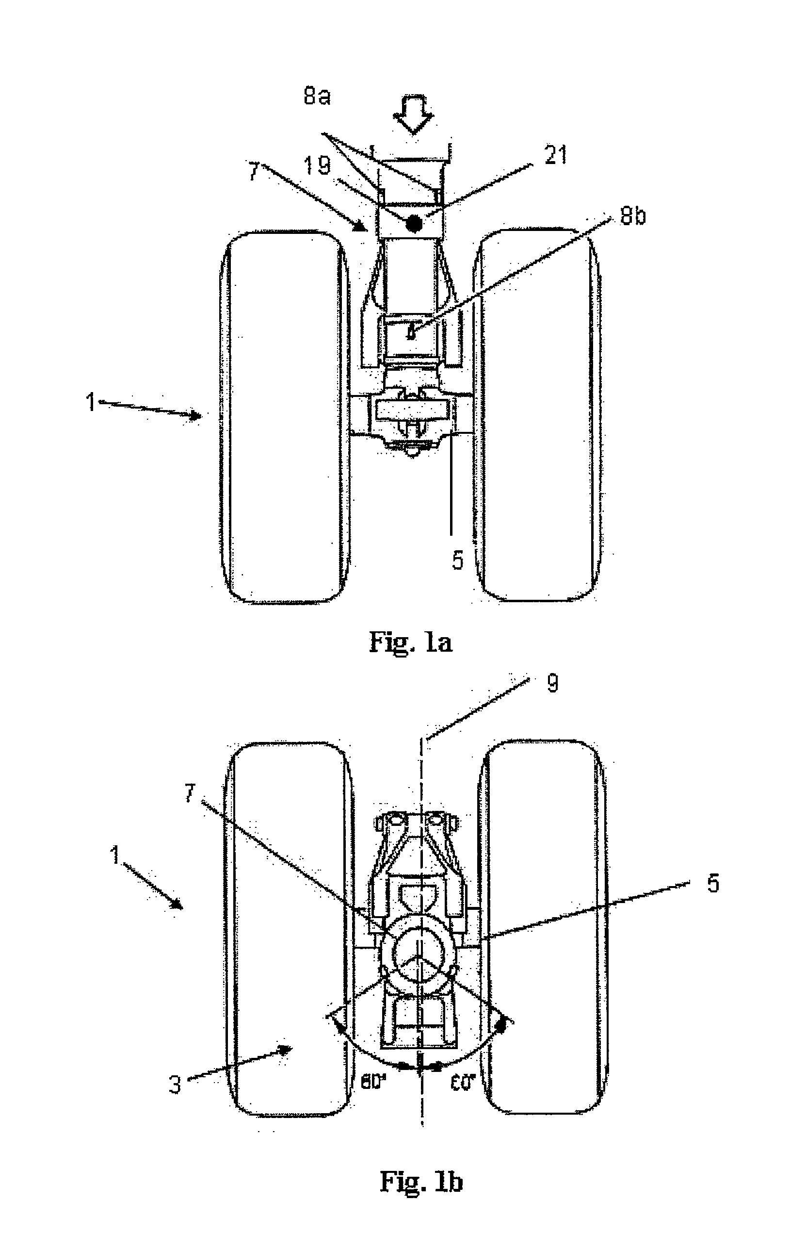
[0045]FIGS. 1a and 1b are views of an aircraft nose landing gear 1 on an aircraft 6 (see FIG. 1c) according to the invention. The nose landing gear comprises two wheels 3 located either side of a central axle 5. The axle 5 is mounted on the end of the landing gear leg 7. The nose landing gear 1 is shown with a steering angle of zero degrees in which the axle 5 is perpendicular to the longitudinal axis 9 of the aircraft. The nose landing gear has a maximum allowable steering angle of 60 degrees, beyond which damage may occur to the landing gear.

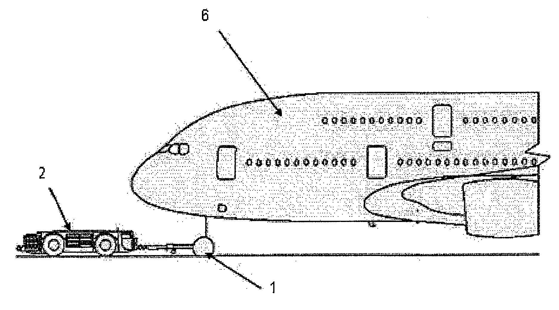
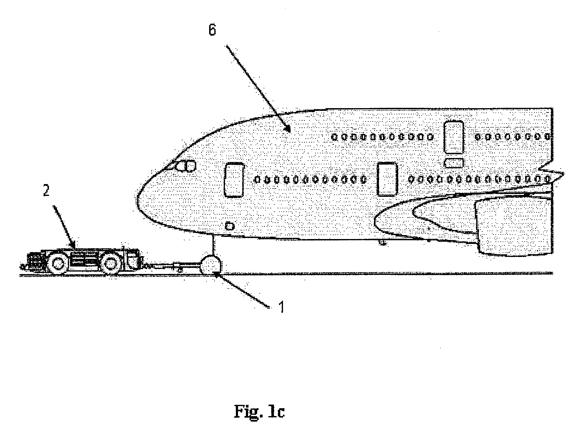
[0046]Referring to FIG. 1c, during on-ground manoeuvres, a towing vehicle 2 engages with the nose landing gear 1. A tow key is inserted into a steering disconnect panel (not shown) to allow certain parts of the landing gear hydraulics to be disconnected (as is conventional in the art). When those hydraulic parts are disconnected, the landing gear is, to some degree, free to rotate under the influence of the tow vehicle. It is therefore possibl...

second embodiment

[0061]FIGS. 3a and 3b are perspective views of an aircraft nose landing gear comprising a steering angle warning system according to the invention. The region enclosed by the thick dashed line of FIG. 3a, is shown in close-up in FIG. 3b.

[0062]The steering angle warning system is primarily as described with reference to the first embodiment except for the changes described below.

[0063]The first signal from the rotation-measuring device is received (via an A / D converter) by a software module (not shown). The software module forms part of the main software system of the aircraft and is arranged to determine, in dependence on the first signal, whether the steering angle is greater than 55 degrees. The software module is arranged to output a control signal to an alarm unit 119 when the steering angle has been determined to be greater than 55 degrees.

[0064]When the control signal is received, an alarm is generated by the strobe light 119 on the landing gear leg. Thus when the steering an...


PUM


Abstract

A steering angle warning system comprising a rotation-measuring unit located on an aircraft, and an alarm unit. The rotation-measuring unit is arranged to output a first signal dependent on the steering angle between a nose landing gear of the aircraft and the longitudinal axis of the aircraft fuselage. The alarm unit is arranged to generate an alarm, in dependence on the first signal, when the steering angle is greater than a predetermined value, for example, 60 degrees. The rotation-measuring unit may also be arranged to perform a function in relation to an aircraft steering system, for example to indicate the steering angle to the pilot during ground manoeuvres.

Description

RELATED APPLICATIONS[0001]The present application is based on International Application Number PCT / GB2007 / 000633 filed Feb. 23, 2007, and claims priority from British Application Number 0606087.5 filed Mar. 27, 2006, the disclosures of which are hereby incorporated by reference herein in their entirety.BACKGROUND OF THE INVENTION[0002]The present invention relates to a steering angle warning system, an aircraft and / or tow vehicle including a steering angle warning system, and a method of warning against excessive steering angle on an aircraft.[0003]Movement of an aircraft on the ground is often effected by a towing tractor engaged with the aircraft nose landing gear. It may be possible for the towing tractor to turn the nose landing gear through an excessive steering angle and damage the nose landing gear assembly.[0004]Some systems are known to provide a warning against excessive steering angle. For example, it is known to have coloured markings on the rotatable leg of the nose lan...

Claims


Application Information

Patent Timeline
Patent Type & Authority Patents(United States)
IPC IPC(8): G08B21/00
CPCB64F1/22B64C25/50
Inventor READ, TERRY GEORGEYIASOUMI, ANDREASSTINCHCOMBE, DAVID GEORGESADLER, ANDREW DAVIDPIDDOCK, ALEX ROBERT
Owner AIRBUS OPERATIONS LTD
Learn More