
Massage machine

a massage machine and motor technology, applied in the field of massage machines, can solve the problems of low torque, difficult to reduce the size and weight of the massage machine itself, and significant load change during treatment, and achieve the effects of low noise, low noise, and small siz

Active Publication Date: 2012-01-10
MATSUSHITA ELECTRIC WORKS LTD
View PDF13 Cites 2 Cited by
  • Summary
  • Abstract
  • Description
  • Claims
  • Application Information

AI Technical Summary

Benefits of technology

"The present invention provides a massage machine using a small-sized and high torque brushless DC motor to drive a heavy load, reducing discomfort due to motor noises and controlling motor rotation speed accurately for a comfortable massage effect. The machine has a driving unit that moves up and down along guide rails on the backrest of the chair, treatment head bases driven in opposite directions, treatment heads supported on the bases, and a control circuit that drives the motors independently for accurate treatment of different body parts. The use of a brushless DC motor with a high output and a control circuit that corrects waveforms of driving signals allows for a small size and high torque output of the motor while achieving low noise and low vibration."

Problems solved by technology

Furthermore, when the user moves the body during treatment, it causes a weight shift, which leads to significant load change during the treatment.
Thus, it has been difficult to reduce the size and weight of the massage machine itself.
Although there is a massage machine using a small sized brushed DC motor, the motor has a low torque, so that it is difficult to obtain sufficient treatment effects.
However, although a brushless DC motor enables to achieve a small sized and high torque (high output) motor, it causes a new problem when used in a massage machine with large load change.
Since these noises are transmitted to a human body via the treatment heads, it causes discomfort to a user when a portion near the head such as neck or shoulder is treated.
However, assuming that a brushless DC motor is used for a massage machine as described above, the sinusoidal wave drive makes it impossible to start or difficult to smoothly start the brushless DC motor because the load is not constant.
Thus, there is a possibility that the user cannot obtain a comfortable massage effect.

Method used


Image

  • Massage machine
  • Massage machine
  • Massage machine

Examples


Embodiment Construction

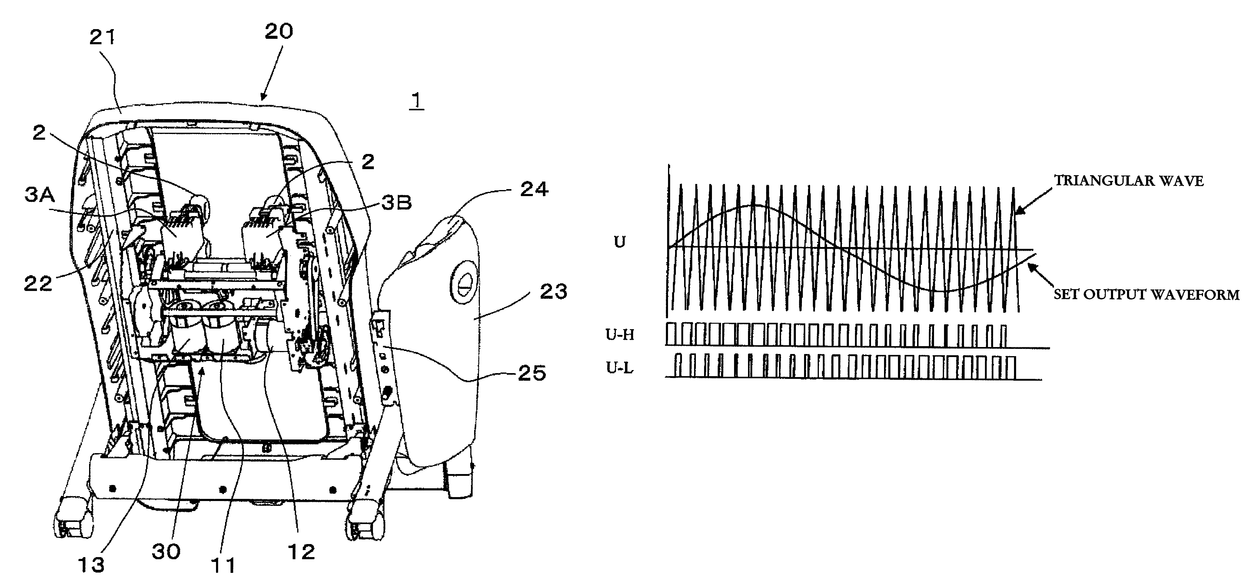
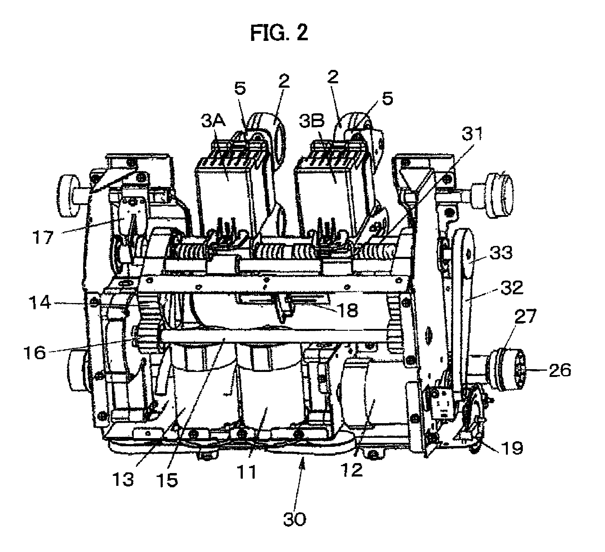
[0023]A massage machine in accordance with an embodiment of the present invention will be described. FIG. 1 shows a configuration of the massage machine in accordance with the present embodiment as seen from a rear side of a backrest thereof. FIG. 2 shows a configuration of a driving unit of the massage machine.

[0024]As shown in FIG. 1, the massage machine 1 in accordance with the present embodiment comprises: a chair 20; a driving unit 30 which itself moves up and down along guide rails 22 provided on a backrest 21 of the chair 20; an operation switch 24 and a control circuit 25 which are provided on armrests 23; and so on.

[0025]The driving unit 30 comprises a first motor 11 that rotates and drives a first driving shaft 26 via a gear mechanism not shown in the figure. Pinions 27 which engage with racks (not shown in the figure) of the guide rails 22 are fixed on the first driving shaft 26. Thus, by switching the first motor 11 between a normal rotation and a reverse rotation, the d...


PUM


Abstract

A massage machine using a small size and high torque brushless DC motor includes a driving unit moved up and down along guide rails of a chair and a first motor for moving the driving unit up and down. A pair of treatment head bases are driven reciprocally in opposite directions to each other; and a second motor reciprocally drives the treatment head bases in opposite directions to each other. Treatment heads are respectively supported by the treatment head bases; and a third motor drives the treatment heads in a plane substantially perpendicular to a backrest. A control circuit drives the respective motors respectively independently of one another. Each motor is a brushless motor. A control circuit corrects, corresponding to a load imposed on the brushless DC motor, a waveform of a drive signal applied to a winding of the brushless DC motor so as to allow a current flowing through the winding of the brushless DC motor to have a substantially sinusoidal waveform making it possible to reduce discomfort due to motor noise, and to accurately control the motor rotation speed.

Description

TECHNICAL FIELD[0001]The present invention relates to a massage machine for driving treatment heads to trace a three-dimensional trajectory so as to perform various treatments.BACKGROUND ART[0002]A massage machine with substantially spherical treatment heads called massage balls driven to trace a three-dimensional trajectory uses, for example, three motors which are driven independently of one another. Treatments such as acupressure, massage and spine stretching are performed by combining an up / down movement along a backrest of a chair, a reciprocal movement in the width direction of the chair (width adjustment) and a revolving movement (back-and-forth movement) of the treatment heads. In recent years, following to complexity of the three-dimensional operations (called hand techniques) of the treatment heads, it is necessary to switch a motor in a short time between a low speed rotation and a high speed rotation, and to frequently switch the motor between a normal rotation and a rev...

Claims


Application Information

Patent Timeline
Patent Type & Authority Patents(United States)
IPC IPC(8): A61H15/00A61H23/02H02K1/27H02K21/16H02M7/537H02P6/06H02P6/08H02P6/17H02P6/28
CPCA61H15/0078A61H2015/0014A61H2201/0149A61H2201/50A61H2203/0431A61H2205/04A61H2205/062A61H2205/081A61H23/0254A61H2201/1215
Inventor TSUKADA, DAISUKEMUTO, MOTOHARUKAJIYAMA, SATOSHIINOUE, HIROKISUZUKI, MASAYUKI
Owner MATSUSHITA ELECTRIC WORKS LTD
Learn More