Selecting a handover algorithm

a handover algorithm and handover technology, applied in the field of wireless communication systems, can solve the problems of reducing customer satisfaction, affecting the service life of customers, and affecting the service life of customers, and achieving the effect of reducing the loss of network capacity, reducing the service life of customers, and increasing interference levels

Inactive Publication Date: 2011-12-20
ALCATEL LUCENT SAS
View PDF10 Cites 10 Cited by
  • Summary
  • Abstract
  • Description
  • Claims
  • Application Information

AI Technical Summary

Problems solved by technology

The coverage area of each cell in the wireless network is typically limited by the propagation loss of radio signals transmitted by base stations that provide coverage to the cell.
For example, mobile units traveling outside the UMTS coverage area will be dropped if they do not perform a handover to the GSM access technology, which may also cause customer satisfaction to fall.
As a result, the compressed mode, and especially the SF / 2 method, can cause significant power variations that result in higher interference levels and network capacity losses.
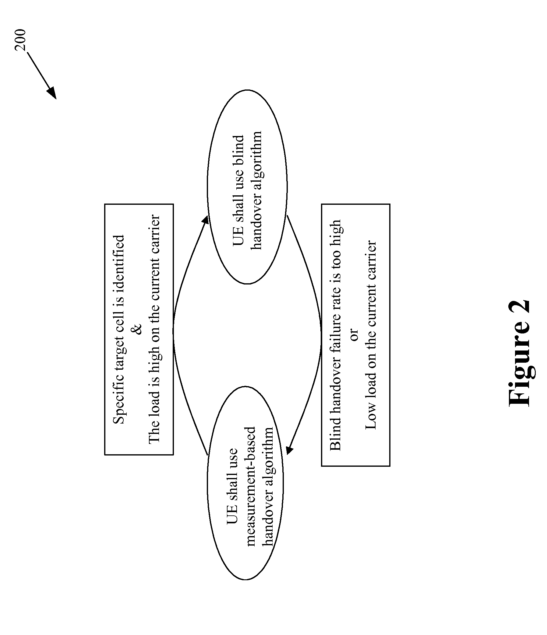
However, no measurements will be performed on the target cells (either the other RAT or a different UMTS carrier) and so the best target cell and the signal quality on the new carrier cannot be determined.
Quantifying the pros and cons of the different handover algorithms upfront is very difficult, if not impossible, and so conventional algorithm selection techniques implement predefined static selection rules that are conservative or defensive.
Conventional algorithm selection techniques are therefore inflexible and do not take into account the fact that both algorithm alternatives have their benefits, too.
The conventional algorithm selection techniques also fail to take into account changing conditions that may affect the selection rules.
When a blind handover has been selected, the absence of target cell measurements in a blind handover may increase the danger that handover might be directed towards an inappropriate target cell, e.g. if the selection process has not been carried out carefully enough and the best target cells have not been selected.
This would have a negative impact on the network performance and could also result in an increased handover failure or call drop rate.
The use of fixed target cell definition may also be a drawback in many situations.
Second, the best target cell(s) will not be dynamically updated during the operational phase.
Thus, existing cells may not be available at all times and new base stations that provide service to new cells may be installed.
This is a very time consuming and costly procedure.

Method used


Image

  • Selecting a handover algorithm
  • Selecting a handover algorithm
  • Selecting a handover algorithm

Examples


Embodiment Construction

[0025]Illustrative embodiments of the invention are described below. In the interest of clarity, not all features of an actual implementation are described in this specification. It will of course be appreciated that in the development of any such actual embodiment, numerous implementation-specific decisions should be made to achieve the developers' specific goals, such as compliance with system-related and business-related constraints, which will vary from one implementation to another. Moreover, it will be appreciated that such a development effort might be complex and time-consuming, but would nevertheless be a routine undertaking for those of ordinary skill in the art having the benefit of this disclosure.

[0026]Portions of the present invention and corresponding detailed description are presented in terms of software, or algorithms and symbolic representations of operations on data bits within a computer memory. These descriptions and representations are the ones by which those ...


PUM


Abstract

The present invention provides methods for selecting a handover algorithm. The methods may include selecting the handover algorithm for a mobile unit based on at least one measurement indicative of a network state. The methods may also include receiving information indicative of the handover algorithm selected based on the measurement(s) indicative of the network state.

Description

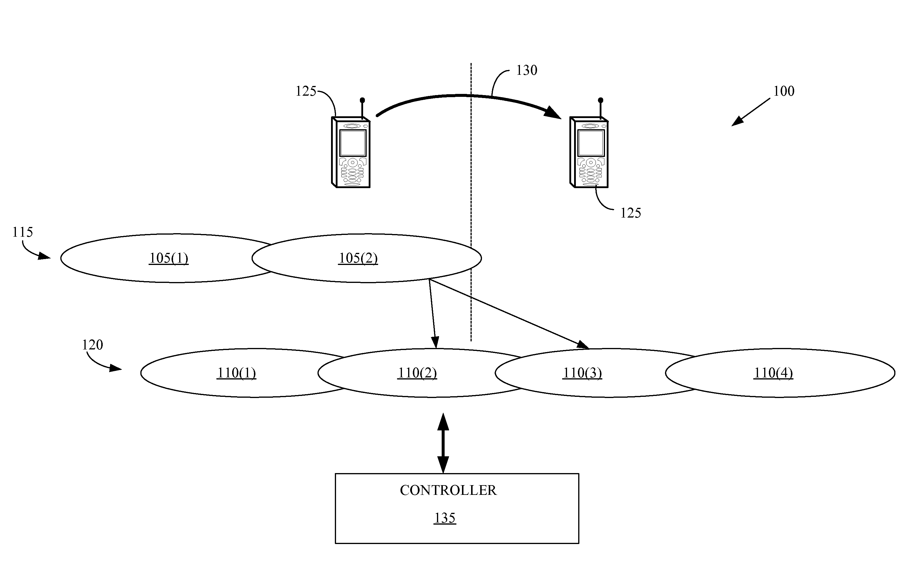
CROSS REFERENCE TO RELATED APPLICATIONS[0001]This application is related to U.S. patent application Ser. No. 11 / 554,642, filed on Oct. 31, 2006.BACKGROUND OF THE INVENTION[0002]1. Field of the Invention[0003]This invention relates generally to communication systems, and, more particularly, to wireless communication systems.[0004]2. Description of the Related Art[0005]The coverage area of a wireless communication system is typically divided into a number of cells, which may be grouped into one or more radio access networks. The coverage area of each cell in the wireless network is typically limited by the propagation loss of radio signals transmitted by base stations that provide coverage to the cell. Thus, the coverage area of each cell is determined by the location and the transmit power of the base station, as well as the topology of the cell and the location of any interfering objects. For example, the coverage area of a cell may be reduced if a building or a mountain is present ...

Claims


Application Information

Patent Timeline
Patent Type & Authority Patents(United States)
IPC IPC(8): H04W4/00
CPCH04W36/24H04W36/14
Inventor BERNHARD, URS PETERZHOU, HAI
Owner ALCATEL LUCENT SAS
Why Eureka
Try Eureka