System and method for acoustic ejection of drops from a thin layer of fluid

a thin layer of fluid and drop technology, applied in the field of drop ejection, can solve the problems of complex high resolution images, high cost, and inability to eject drops, and achieve the effects of avoiding ejection, avoiding ejection, and avoiding ejection

Inactive Publication Date: 2011-12-20
PALO ALTO RES CENT INC
View PDF11 Cites 0 Cited by
  • Summary
  • Abstract
  • Description
  • Claims
  • Application Information

AI Technical Summary

Problems solved by technology

An electro-acoustic transducer positioned at the bottom of a fluid container generates a ripple wave, and the wave propagates through the fluid reservoir, resulting in a disturbance of the fluid reservoir.
However, Elrod et al. is directed to the formation of complex high resolution images and requires employing costly complex switching and imaging electronics and sophisticated operations to control the capillary waves for individual drop ejection and placement.
Thus, such devices do not lend themselves to industrial uses which would have need for ejectors able to generate simple patterns by use of a low cost printhead design, which permit for simplified control operations.

Method used


Image

  • System and method for acoustic ejection of drops from a thin layer of fluid
  • System and method for acoustic ejection of drops from a thin layer of fluid
  • System and method for acoustic ejection of drops from a thin layer of fluid

Examples


Embodiment Construction

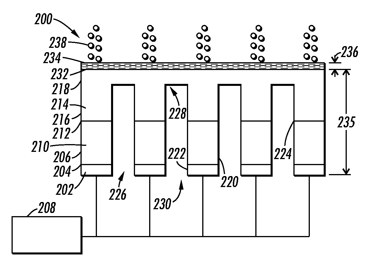
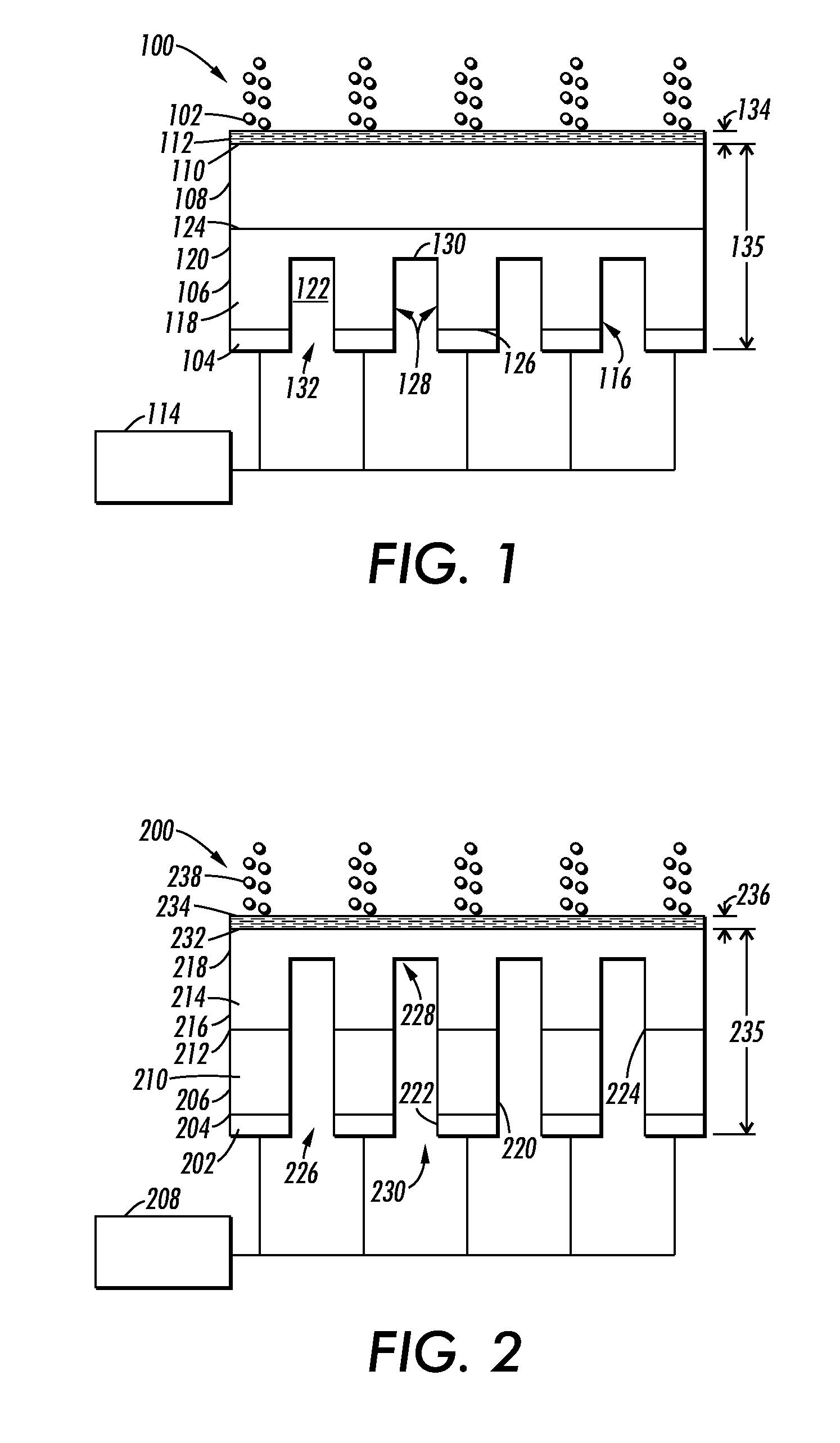
[0011]The subject application relates to ejecting drops from a thin layer of fluid. An apparatus comprises a segmented metal support structure, in which drops are ejected in areas of the thin layer of fluid that are above extending metal elements of the segmented metal support structure. The areas of the thin layer of fluid that are not above extending metal elements experience less agitation than areas of the thin layer of fluid that are above the extending metal elements.

[0012]Referring to FIG. 1, an apparatus 100 such as a drop ejector for ejecting and depositing thin uniform films of liquid drops 102 in a predetermined pattern is shown. The apparatus 100 comprises sound wave generating devices 104, such as but not limited to, piezoelectric elements 104 in operative connection with a support structure 106, which in this embodiment is a partially segmented support structure. The support structure may be made of metal or other material which provides a path for generated sound wave...


PUM


Abstract

Features described herein relate to ejecting drops from a thin layer of fluid. Piezoelectric elements can generate a uniform high acoustic field, which is transferred through a segmented metal support structure and an acoustic horn. The sound waves generate capillary waves on a thin layer of fluid on a top surface of the acoustic horn. At sufficiently high amplitudes, the capillary waves begin to break apart, resulting in the ejection of drops from the thin layer of fluid.

Description

BACKGROUND[0001]The subject application relates to drop ejection, and in particular to pattern ejection of a mist of very small droplets from capillary waves.[0002]An example of a drop ejector which operates to eject droplets by controlling capillary wave action is set forth in U.S. Pat. No. 5,194,880, titled, “Multi-Electrode, Focused Capillary Wave Energy Generator”, to Elrod et al., issued Mar. 16, 1993, which discloses a capillary wave printer that can generate a ripple wave at the top of a fluid container. An electro-acoustic transducer positioned at the bottom of a fluid container generates a ripple wave, and the wave propagates through the fluid reservoir, resulting in a disturbance of the fluid reservoir. Consequently, the top of the fluid reservoir can begin to emit droplets of fluid due to the vibrations imparted by the piezoelectric pushers.[0003]However, Elrod et al. is directed to the formation of complex high resolution images and requires employing costly complex swit...

Claims


Application Information

Patent Timeline
Patent Type & Authority Patents(United States)
IPC IPC(8): B41J2/045
CPCB41J2/14008
Inventor ELROD, SCOTT A.
Owner PALO ALTO RES CENT INC
Why Eureka
Try Eureka